


How Do Brushless DC Motors Work
2025-06-19
How Do Brushless DC Motors Work?
In the rapidly evolving landscape of electrical engineering, brushless DC (BLDC) motors have emerged as a revolutionary force, powering a vast array of applications from consumer electronics to high - end industrial machinery. Unlike their brushed counterparts, BLDC motors offer enhanced efficiency, longer lifespan, and precise control. To truly appreciate their capabilities, it's essential to understand the intricate mechanisms behind their operation. This blog post will take you on a deep dive into how brushless DC motors work, exploring their structure, key components, working principles, and control methods.
Understanding the Basics of Brushless DC Motors
Defining Brushless DC Motors
A brushless DC motor is an electronically commutated electric motor that operates on direct current power. The defining characteristic of BLDC motors is the absence of mechanical brushes and a commutator, which are replaced by an electronic control system. Instead of relying on physical contact to reverse the current direction in the motor windings, BLDC motors use sensors (or sensorless algorithms) and solid - state electronics, such as inverters, to achieve commutation. This fundamental difference in design is what sets BLDC motors apart and gives them their unique advantages.
Comparison with Brushed DC Motors
To better understand the workings of BLDC motors, it's helpful to compare them with brushed DC motors. In brushed DC motors, mechanical brushes make contact with the commutator, which physically switches the current in the armature windings as the motor rotates. This process leads to wear and tear of the brushes over time, generating electrical arcing and electromagnetic interference (EMI). In contrast, BLDC motors eliminate these issues, resulting in a more reliable, efficient, and maintenance - free operation. The electronic commutation in BLDC motors allows for more precise control of the motor's speed, torque, and direction, making them suitable for a wider range of applications.
Structure of a Brushless DC Motor
Stator
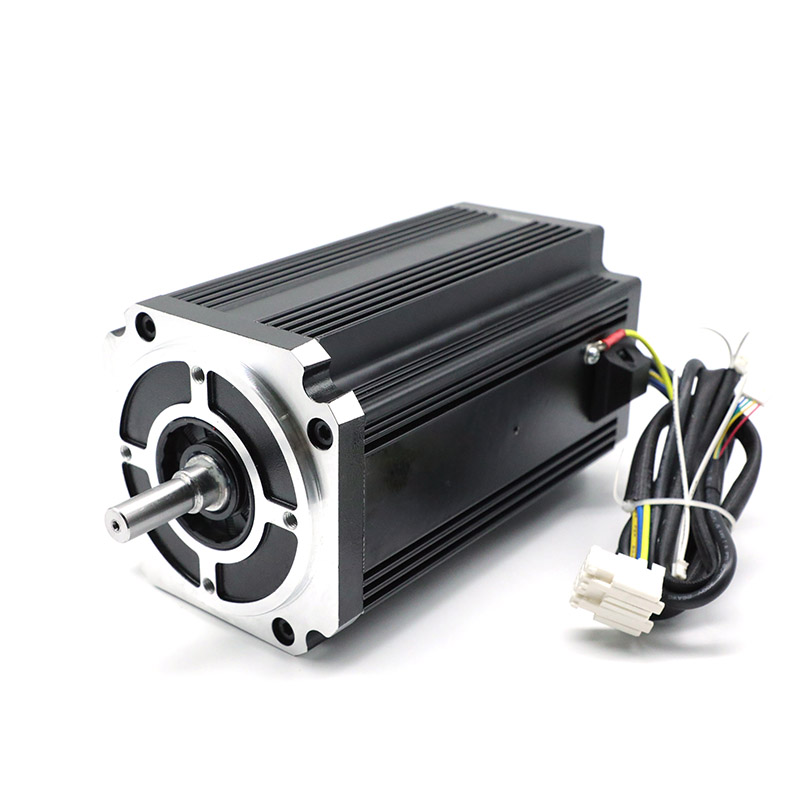
The stator is the stationary part of a BLDC motor and plays a crucial role in generating the magnetic field. It typically consists of multiple coils (windings) arranged in a specific pattern, usually in three phases for most common BLDC motors. These windings are made of insulated copper wire and are connected to an external power source through an electronic controller. When an electric current flows through the stator windings, a rotating magnetic field is created. The design of the stator, including the number of turns in the windings, the wire gauge, and the winding configuration, significantly impacts the motor's performance characteristics, such as torque, speed, and efficiency.
Rotor
The rotor is the rotating part of the BLDC motor and is equipped with permanent magnets. These magnets are usually made from high - performance magnetic materials like neodymium - iron - boron (NdFeB), which provide a strong and stable magnetic field. The arrangement of the magnets on the rotor can vary, with common configurations including surface - mounted magnets (SMPM) and interior permanent magnet (IPM) designs. In the SMPM configuration, the magnets are attached to the outer surface of the rotor, while in the IPM design, the magnets are embedded inside the rotor. The interaction between the magnetic field of the rotor's permanent magnets and the rotating magnetic field generated by the stator is what drives the rotation of the motor.
Electronic Controller
The electronic controller is the brain of the BLDC motor system. It receives input signals, such as speed commands or position feedback, and uses this information to control the flow of current to the stator windings. The controller typically includes a microcontroller or a digital signal processor (DSP) that implements the commutation algorithm. This algorithm determines the precise timing and sequence for switching the current in the stator windings to maintain the rotation of the motor. Additionally, the controller may incorporate features for speed regulation, torque control, and protection against overcurrent, overvoltage, and overheating.
Sensors (Optional)
Some BLDC motors use sensors to provide information about the rotor's position and speed. Hall effect sensors are commonly used for this purpose. These sensors detect the position of the rotor's magnets and send signals to the controller, which then initiates the appropriate current switching in the stator windings. Encoder sensors can also be used, especially in applications that require high - precision position and speed feedback, such as servo systems. However, sensorless BLDC motor control techniques have been developed, which estimate the rotor's position based on the back electromotive force (EMF) generated in the stator windings, eliminating the need for additional sensors and reducing costs and complexity.
Working Principles of Brushless DC Motors
The Commutation Process
The commutation process is the heart of how a BLDC motor works. In a three - phase BLDC motor, for example, the electronic controller sequentially switches the current in the three stator windings in a specific sequence. This sequence is carefully controlled to create a rotating magnetic field that interacts with the permanent magnets on the rotor, causing the rotor to rotate. When the controller supplies current to one phase of the stator windings, a magnetic field is generated. The attraction and repulsion forces between this magnetic field and the magnetic field of the rotor's magnets cause the rotor to move. As the rotor rotates, the position of the magnets relative to the stator windings changes. The sensors (if present) or the sensorless control algorithm detect this change and signal the controller to switch the current to the next phase of the stator windings, ensuring continuous rotation.
Interaction between Stator and Rotor
The interaction between the stator and the rotor is based on the principle of electromagnetic attraction and repulsion. When the stator windings are energized, they create a magnetic field. The permanent magnets on the rotor are then attracted to the opposite poles of the stator's magnetic field and repelled by the like poles. This force causes the rotor to rotate. As the rotor moves, the electronic controller continuously adjusts the current in the stator windings to maintain the interaction between the magnetic fields, keeping the rotor in motion. The speed of the motor depends on the frequency of the current switching in the stator windings, while the torque is related to the magnitude of the current flowing through the windings.
Speed and Torque Control in Brushless DC Motors
Speed Control
The speed of a BLDC motor can be precisely controlled by adjusting the frequency of the current supplied to the stator windings. By increasing the frequency, the rotating magnetic field generated by the stator rotates faster, which in turn increases the speed of the rotor. Conversely, decreasing the frequency slows down the motor. This can be achieved through various control methods, such as pulse - width modulation (PWM). In PWM control, the controller varies the width of the electrical pulses sent to the stator windings. A higher duty cycle (longer pulses) results in more power being delivered to the motor, increasing its speed, while a lower duty cycle reduces the speed.
Torque Control
Torque control in BLDC motors is achieved by regulating the magnitude of the current flowing through the stator windings. According to the principle of electromagnetic force, a higher current results in a stronger magnetic field, which generates more torque. The electronic controller can adjust the current based on the load requirements of the application. For example, when a heavier load is applied to the motor, the controller increases the current to provide the necessary torque to maintain the desired speed. This can be done using feedback control systems that monitor the motor's performance and adjust the current in real - time.
Real - World Applications and How the Working Principles Apply
Consumer Electronics
In consumer electronics, such as computer fans and robotic vacuum cleaners, the precise control and efficiency of BLDC motors are highly valued. In a computer fan, the electronic controller adjusts the speed of the motor based on the temperature of the computer components. When the temperature rises, the controller increases the frequency of the current to the stator windings, speeding up the fan to provide more cooling. The commutation process ensures smooth and quiet operation, without the noise and wear associated with brushed motors. In robotic vacuum cleaners, the BLDC motor's ability to provide accurate torque control allows for precise navigation and cleaning performance, as the motor can adjust its power output based on the surface being cleaned.
Industrial Automation
In industrial automation, BLDC motors are used in a variety of applications, such as conveyor belts and robotic arms. In a conveyor belt system, the speed of the BLDC motor needs to be controlled accurately to ensure the smooth movement of materials. The controller adjusts the frequency of the current to maintain the desired speed, even when the load on the conveyor changes. For robotic arms, precise torque control is essential for accurate movement and positioning. The electronic controller can provide the necessary torque at different joints of the robotic arm, enabling it to perform complex tasks with high precision. The commutation process in these industrial applications ensures reliable and continuous operation of the BLDC motors, reducing the need for frequent maintenance.
Understanding how brushless DC motors work is essential for engineers, designers, and enthusiasts alike. Their unique combination of electronic commutation, precise control, and high - efficiency operation makes them a versatile and powerful choice for a wide range of applications. From the basic structure and working principles to the advanced control methods and real - world applications, BLDC motors continue to shape the future of electrical engineering. As technology continues to advance, we can expect even more innovative uses of BLDC motors, further expanding their capabilities and impact.
How to Construct a DC Motor
What is a Brushed DC Motor
Related Article

Brushless DC (BLDC) motors are widely used in EVs, drones, industrial machinery, and robotics for their efficiency and long lifespan. Unlike brushed motors—where reversing direction only requires swapping power leads—BLDC motors rely on electronic commutation, making direction reversal more nuanced.
How to Reverse Direction in Brushless Motors
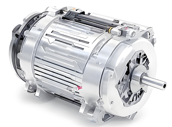
Brushed and brushless DC motors are two of the most common electric motor designs, powering everything from toys to electric vehicles. While both convert electrical energy to mechanical motion, their internal structures, performance, and use cases differ drastically.
What’s the Difference Between a Brushed and Brushless Motor
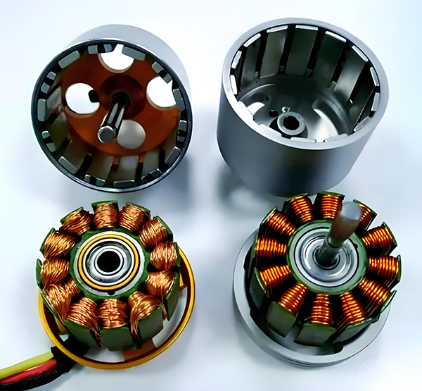
Brushed DC motors are reliable, but wear and tear over time can lead to failure. Whether you’re troubleshooting a power tool, household appliance, or industrial conveyor motor, knowing the signs of a bad brushed motor saves time and prevents further damage.
How to Know If a Brushed Motor Is Bad
