


How Does a DC Electric Motor Work
2025-06-07
How Does a DC Electric Motor Work?
In the realm of electrical engineering and everyday technology, DC (Direct Current) electric motors play a crucial and omnipresent role. From the motors powering the windshield wipers in your car to the ones inside your electric toothbrush, understanding how these motors function is not only fascinating but also essential for anyone interested in the inner workings of modern devices. In this in - depth blog post, we will meticulously dissect the components, principles, and processes that enable a DC electric motor to convert electrical energy into mechanical energy.
1. Fundamental Components of a DC Electric Motor
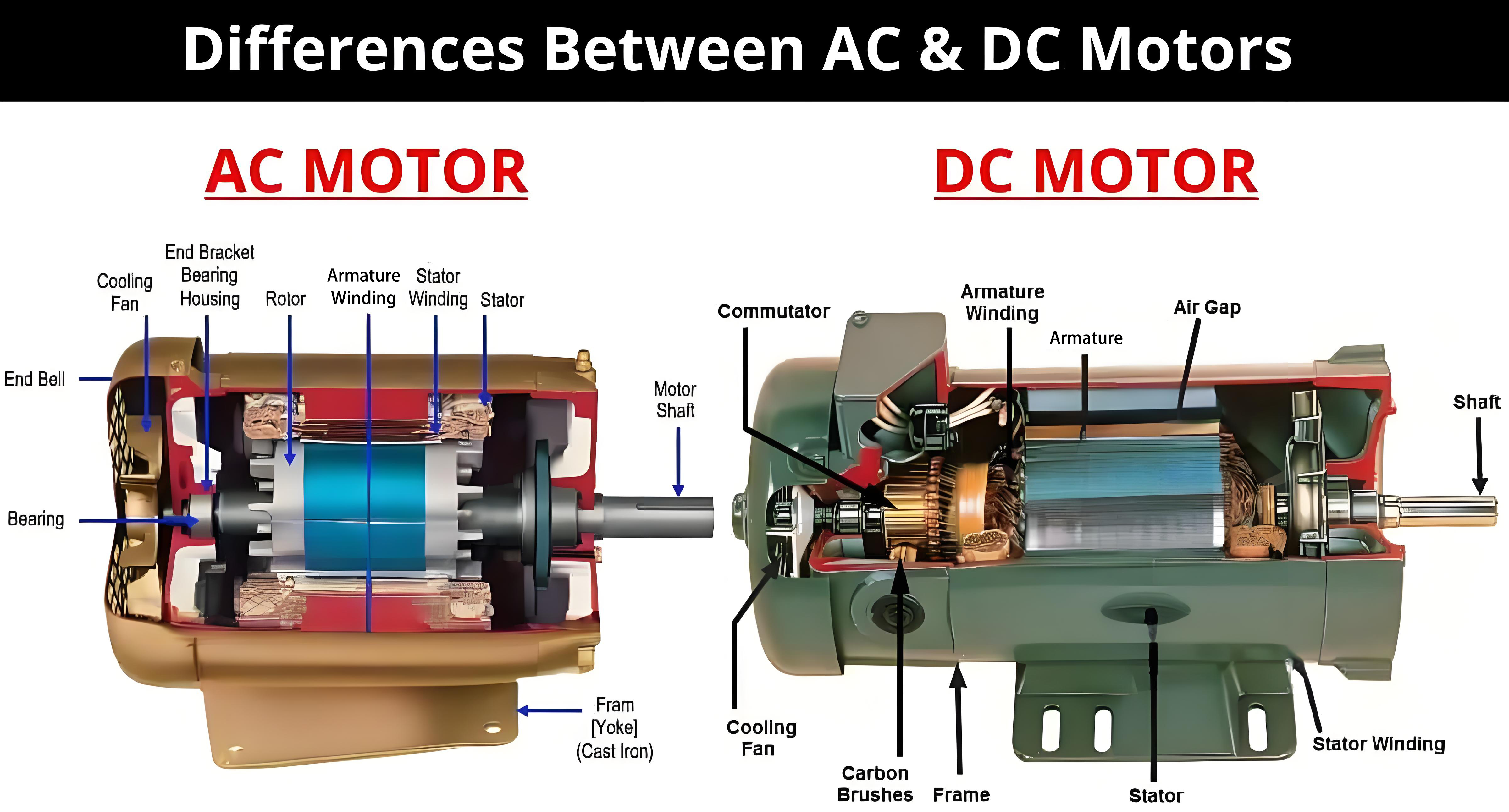
1.1 Stator
The stator is the stationary part of a DC electric motor, serving as the foundation upon which the motor's operation is built. It typically consists of a frame made of ferromagnetic material, which helps to concentrate and guide the magnetic field. Embedded within the stator are field coils or permanent magnets. In motors with field coils, an electric current is passed through these coils, generating a magnetic field. The strength of this magnetic field can be adjusted by varying the current flowing through the coils. In contrast, motors with permanent magnets utilize the fixed magnetic field produced by materials like neodymium - iron - boron or ceramic magnets, which offer a more straightforward and often cost - effective solution for many applications.
1.2 Rotor (Armature)
The rotor, also known as the armature, is the rotating part of the motor. It comprises a core made of laminated iron sheets, which are stacked together to reduce eddy current losses. Wound around this core are the armature coils, which are the key elements responsible for interacting with the magnetic field generated by the stator. The armature is mounted on a shaft, which is connected to the load that the motor is intended to drive, such as a fan blade or a wheel.
1.3 Commutator
The commutator is a distinctive and crucial component of a DC electric motor. It is a cylindrical structure, usually made of segments of copper separated by insulating materials. The armature coils are connected to the commutator segments, and its main function is to reverse the direction of the current in the armature coils at regular intervals. This reversal of current is essential for the continuous rotation of the motor, as we will explore in more detail later.
1.4 Brushes
Brushes are another vital part of the DC motor system. These are typically made of carbon or a carbon - graphite composite material. The brushes make physical contact with the commutator segments and serve as the electrical connection between the external power source and the armature coils. As the commutator rotates, the brushes slide over the segments, ensuring a continuous flow of current to the armature while also facilitating the necessary current reversal.
2. The Electromagnetic Principles Underlying DC Motor Operation
2.1 The Lorentz Force
At the heart of how a DC electric motor works lies the Lorentz force. According to this principle, when a current - carrying conductor is placed in a magnetic field, it experiences a force. The direction of this force is determined by the right - hand rule: if you point your thumb in the direction of the current and your fingers in the direction of the magnetic field, then the palm of your hand will indicate the direction of the force. In a DC motor, the armature coils act as these current - carrying conductors, and the magnetic field is provided by the stator. The Lorentz force causes the armature to experience a torque, which results in its rotation.
2.2 Magnetic Field Interaction
The interaction between the magnetic field of the stator and the magnetic field generated by the current - carrying armature coils is what drives the motor. When current flows through the armature coils, they create their own magnetic fields. These fields interact with the magnetic field of the stator, either attracting or repelling it, depending on the relative orientation of the fields. This interaction generates the necessary force to rotate the armature.
3. The Step - by - Step Working Process of a DC Electric Motor
3.1 Initial Current Flow
When a DC power source is connected to the motor, current begins to flow through the brushes and into the commutator. The commutator then directs the current into the appropriate armature coils based on its position. At this stage, the armature coils are positioned in the magnetic field of the stator, and the current flowing through them causes a magnetic field to be generated around the coils.
3.2 Torque Generation
As a result of the interaction between the magnetic field of the stator and the magnetic field of the armature coils, a torque is generated. This torque acts on the armature, causing it to start rotating. The direction of the rotation depends on the direction of the current in the armature coils and the orientation of the magnetic field of the stator.
3.3 Commutator Action
As the armature rotates, the commutator plays its crucial role. The segments of the commutator move in relation to the brushes, and at specific points, the brushes make contact with different segments. This change in contact reverses the direction of the current in the armature coils. For example, when one side of the armature coil is moving away from the stator's magnetic field, reversing the current ensures that the force acting on the coil continues to act in the direction that promotes rotation. This continuous reversal of current, facilitated by the commutator, allows the armature to keep rotating.
3.4 Continuous Rotation
With each rotation of the armature, the commutator repeats the process of reversing the current in the armature coils. This continuous cycle of torque generation, current reversal, and further torque generation enables the motor to maintain a steady and continuous rotation, converting the electrical energy from the power source into the mechanical energy required to drive the load.
4. Controlling and Regulating the Speed of a DC Electric Motor
4.1 Voltage Control
One of the most common methods of controlling the speed of a DC electric motor is by adjusting the voltage supplied to the motor. According to the motor's speed - voltage relationship, increasing the voltage will generally increase the speed of the motor, while decreasing the voltage will slow it down. This can be achieved using various techniques, such as employing a variable - voltage power supply or a voltage regulator circuit.
4.2 Field Weakening
In some cases, field weakening can be used to control the speed of a DC motor. By reducing the strength of the magnetic field generated by the stator (either by decreasing the current in the field coils or using a different configuration), the motor can operate at higher speeds. However, field weakening also reduces the torque - producing capability of the motor, so it needs to be carefully applied depending on the specific requirements of the application.
4.3 Pulse - Width Modulation (PWM)
Pulse - width modulation is a widely used technique for speed control. PWM works by rapidly switching the power supply to the motor on and off at a high frequency. By varying the width of the "on" pulses relative to the total cycle time (the duty cycle), the average voltage applied to the motor can be adjusted. A higher duty cycle results in a higher average voltage and thus a higher speed, while a lower duty cycle leads to a lower speed. PWM offers precise control over the motor speed and is commonly used in many modern DC motor control systems.
In conclusion, the operation of a DC electric motor is a fascinating interplay of electrical, magnetic, and mechanical principles. From the fundamental components like the stator, rotor, commutator, and brushes to the electromagnetic forces at work and the control mechanisms for speed regulation, each aspect contributes to the motor's ability to efficiently convert electrical energy into mechanical motion. Understanding these workings not only provides insight into the technology that surrounds us but also paves the way for further advancements in motor design and application.
以上详细介绍了直流电机的工作原理。如果你想对某部分内容深入探讨,或者有增减知识点、调整篇幅等需求,欢迎随时告诉我。
What is a DC Electric Motor
How Do Brushless DC Electric Motors Work
Related Article

Brushless DC (BLDC) motors are widely used in EVs, drones, industrial machinery, and robotics for their efficiency and long lifespan. Unlike brushed motors—where reversing direction only requires swapping power leads—BLDC motors rely on electronic commutation, making direction reversal more nuanced.
How to Reverse Direction in Brushless Motors
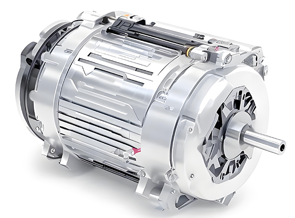
Brushed and brushless DC motors are two of the most common electric motor designs, powering everything from toys to electric vehicles. While both convert electrical energy to mechanical motion, their internal structures, performance, and use cases differ drastically.
What’s the Difference Between a Brushed and Brushless Motor
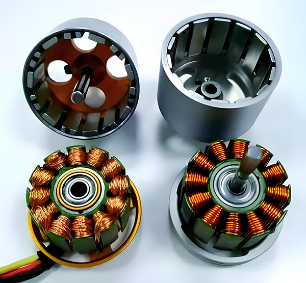
Brushed DC motors are reliable, but wear and tear over time can lead to failure. Whether you’re troubleshooting a power tool, household appliance, or industrial conveyor motor, knowing the signs of a bad brushed motor saves time and prevents further damage.
How to Know If a Brushed Motor Is Bad
