


How Does a Harmonic Drive Work: Unveiling the Mechanics of Strain Wave Gearing
2025-05-21
How Does a Harmonic Drive Work: Unveiling the Mechanics of Strain Wave Gearing
In the realm of precision mechanical engineering, the harmonic drive stands as a revolutionary innovation that has transformed the way we approach power transmission and motion control. Also known as a strain wave gear, this unique device offers unparalleled accuracy, compactness, and reliability, making it a preferred choice in a wide range of applications, from robotics and aerospace to medical equipment and semiconductor manufacturing. In this blog post, we will embark on a detailed exploration of how a harmonic drive works, dissecting its key components, and understanding the principles behind its operation.
Understanding the Basics: What is a Harmonic Drive?
At its core, a harmonic drive is a type of mechanical gear system that uses flexible components to transmit motion and torque. Unlike traditional gear systems that rely on rigid teeth meshing together, a harmonic drive operates on the principle of elastic deformation, allowing for smooth, backlash - free motion and high torque transmission capabilities. The term “harmonic” in its name refers to the sinusoidal motion of its components, which is essential for its operation.
The harmonic drive was first developed in the 1950s by C.W. Musser, who patented the technology in 1957. Since then, it has undergone continuous refinement and improvement, becoming an indispensable part of modern precision engineering. Its unique design and operating principles have made it a game - changer in industries where high precision, compact size, and reliability are of utmost importance.
Key Components of a Harmonic Drive
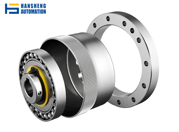
To understand how a harmonic drive works, it is crucial to familiarize ourselves with its three main components: the wave generator, the flexspline, and the circular spline.
The Wave Generator
The wave generator is the driving component of the harmonic drive system. It is typically an elliptical - shaped cam or a ball - bearing - mounted ellipse that, when rotated, deforms the flexspline into an elliptical shape. The wave generator is usually connected to the input shaft, which provides the rotational energy to the system. As the wave generator rotates, it creates a traveling wave of deformation in the flexspline, which is the key to the harmonic drive's operation.
The Flexspline
The flexspline is a thin - walled, cup - shaped component made of a flexible material, usually steel or a high - strength alloy. It has external teeth that are designed to mesh with the internal teeth of the circular spline. When the wave generator rotates, it causes the flexspline to flex and deform elastically, changing its shape from circular to elliptical. This deformation allows the teeth of the flexspline to engage with the teeth of the circular spline at specific points, enabling the transmission of motion and torque.
The Circular Spline
The circular spline is a rigid, ring - shaped component with internal teeth. It is fixed in place and serves as the stationary part of the harmonic drive system. The number of teeth on the circular spline is slightly greater than the number of teeth on the flexspline. This difference in tooth count is what enables the harmonic drive to achieve its high gear reduction ratios.
The Working Principle of a Harmonic Drive
Now that we have a clear understanding of the key components, let's dive into the working principle of a harmonic drive.
Initial Setup
When the wave generator is at rest, the flexspline is in its natural circular shape, and there is no meshing between its teeth and the teeth of the circular spline. As the wave generator starts to rotate, it gradually deforms the flexspline into an elliptical shape. The long axis of the ellipse aligns with the major axis of the wave generator, while the short axis aligns with the minor axis.
Meshing and Motion Transmission
As the wave generator continues to rotate, the elliptical deformation of the flexspline causes its teeth to mesh with the teeth of the circular spline at two opposite points along the major axis of the ellipse. At these points, the teeth of the flexspline and the circular spline engage, allowing torque to be transmitted from the wave generator (input) to the flexspline (output).
As the wave generator rotates further, the point of meshing between the flexspline and the circular spline moves in a circular path around the circumference of the splines. This continuous movement of the meshing point creates a traveling wave of deformation in the flexspline, which results in a smooth and continuous rotation of the flexspline.
Gear Reduction
The gear reduction in a harmonic drive is achieved due to the difference in the number of teeth between the circular spline and the flexspline. For example, if the circular spline has 100 teeth and the flexspline has 98 teeth, for every full rotation of the wave generator, the flexspline will rotate by two teeth relative to the circular spline. This results in a gear reduction ratio of 100/2 = 50:1. The high gear reduction ratios achievable with harmonic drives make them ideal for applications where high torque at low speeds is required.
Backlash - Free Operation
One of the most significant advantages of harmonic drives is their backlash - free operation. Backlash, which is the play or clearance between meshing gears, can cause inaccuracies in motion control and reduce the overall efficiency of a gear system. In a harmonic drive, the continuous elastic deformation of the flexspline ensures that there is always positive tooth engagement between the flexspline and the circular spline, eliminating backlash and providing precise and repeatable motion control.
Applications of Harmonic Drives
The unique characteristics of harmonic drives, such as high precision, compact size, and backlash - free operation, have led to their widespread adoption in various industries.
Robotics
In robotics, harmonic drives are used in joints to provide precise and smooth motion control. The high torque - to - size ratio of harmonic drives allows robots to perform complex tasks with high accuracy, making them essential components in industrial robots, service robots, and humanoid robots.
Aerospace
In the aerospace industry, where weight, size, and reliability are critical factors, harmonic drives are used in satellite positioning systems, antenna pointing mechanisms, and aircraft control surfaces. Their compact design and high precision make them suitable for applications where space is limited and accurate motion control is required.
Medical Equipment
Harmonic drives are also used in medical equipment, such as surgical robots, imaging systems, and diagnostic devices. The backlash - free operation and high precision of harmonic drives are crucial for performing delicate medical procedures with accuracy and minimizing patient trauma.
Semiconductor Manufacturing
In semiconductor manufacturing, where precision is of the utmost importance, harmonic drives are used in wafer handling systems, lithography equipment, and inspection systems. Their ability to provide smooth and accurate motion control ensures the production of high - quality semiconductor chips.
In conclusion, the harmonic drive, or strain wave gear, is a remarkable piece of engineering that has revolutionized the field of precision motion control. By understanding its key components and working principles, we can appreciate the ingenuity behind its design and the many benefits it offers. From robotics and aerospace to medical equipment and semiconductor manufacturing, harmonic drives continue to play a vital role in advancing technology and enabling the development of more precise, efficient, and reliable systems. As technology continues to evolve, we can expect to see even more innovative applications of harmonic drives in the future.
What is DLC Coating
What is a CNC Machine
Related Article

Brushless DC (BLDC) motors are widely used in EVs, drones, industrial machinery, and robotics for their efficiency and long lifespan. Unlike brushed motors—where reversing direction only requires swapping power leads—BLDC motors rely on electronic commutation, making direction reversal more nuanced.
How to Reverse Direction in Brushless Motors
Brushed and brushless DC motors are two of the most common electric motor designs, powering everything from toys to electric vehicles. While both convert electrical energy to mechanical motion, their internal structures, performance, and use cases differ drastically.
What’s the Difference Between a Brushed and Brushless Motor
Brushed DC motors are reliable, but wear and tear over time can lead to failure. Whether you’re troubleshooting a power tool, household appliance, or industrial conveyor motor, knowing the signs of a bad brushed motor saves time and prevents further damage.
How to Know If a Brushed Motor Is Bad
