


How Does a Photoelectric Sensor Work
2025-07-03
How Does a Photoelectric Sensor Work?
In the world of industrial automation, smart devices, and precision engineering, photoelectric sensors serve as the "eyes" of machines, enabling them to detect objects without physical contact. But have you ever wondered about the intricate mechanisms behind their ability to "see"? While we’ve explored what photoelectric sensors are, this article dives deep into the question: How does a photoelectric sensor work? We’ll break down the core working principles, step-by-step detection processes, key technical concepts, and how different sensor types operate in real-world scenarios. Whether you’re an engineer troubleshooting a production line or a student curious about sensor technology, understanding their operational mechanics is essential for leveraging their full potential.
The Foundation of Photoelectric Sensing: Basic Components and Core Concept
What Drives a Photoelectric Sensor?
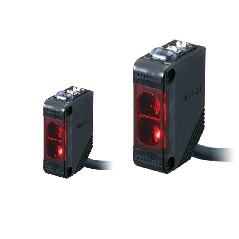
At its core, a photoelectric sensor operates on the principle of light-based detection. It uses a combination of components to emit, transmit, and receive light, translating optical signals into electrical outputs. The three primary components are:
- Emitter (Transmitter): Generates a light beam, typically using LEDs (for general purposes), laser diodes (for precision), or halogen lamps (for high-intensity applications).
- Receiver (Detector): Captures the emitted light, using photodiodes, phototransistors, or photomultiplier tubes to convert light energy into an electrical signal.
- Signal Processing Circuit: Compares the received light intensity to a predefined threshold and triggers an output (digital or analog) when a change is detected.
The magic lies in how these components collaborate to interpret light behavior—whether an object blocks the beam, reflects it, or scatters it—into actionable data.
The Step-by-Step Detection Process: How Light Becomes a Signal
1. Light Emission: Setting the Beam in Motion
The emitter starts by projecting a light beam in a specific direction. This beam can be:
- Continuous: A steady stream of light (common in simple sensors).
- Pulsed/Modulated: Flashing at a specific frequency (e.g., 1kHz to 100kHz), which is critical for reducing ambient light interference.
Modulated light is particularly important in noisy environments. By encoding the light with a unique frequency, the receiver can filter out static light sources (like room lighting or sunlight) that don’t match this frequency, ensuring only the sensor’s own beam is detected.
2. Light Interaction: The Object’s Role in the Beam’s Path
When the light beam encounters an object, one of three interactions occurs, depending on the sensor type:
A. Beam Interruption (Through-Beam Mode)
- What Happens: The emitter and receiver are positioned facing each other. An object passing between them blocks the direct beam, reducing the light reaching the receiver.
- Detection Trigger: The receiver senses a drop in light intensity below a threshold, signaling the object’s presence.
B. Beam Reflection (Retroreflective Mode)
- What Happens: The emitter and receiver are housed together, aimed at a retroreflective target (a special mirror that bounces light back along the same path). An object between the sensor and target partially or fully blocks the reflected beam.
- Detection Trigger: Reduced reflected light intensity prompts the receiver to generate a signal.
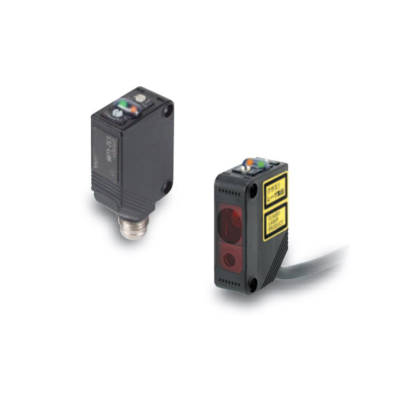
C. Beam Scattering (Diffuse Reflection Mode)
- What Happens: The emitter sends a beam, and the receiver—angled to the emitter—detects light scattered (diffused) off the object’s surface.
- Detection Trigger: When the scattered light intensity exceeds the sensor’s sensitivity threshold, the object is detected.
3. Signal Generation: From Light to Electricity
The receiver converts the incoming light into an electrical signal through photodetection:
- Photodiodes: Generate a current proportional to light intensity, used in analog sensors for distance measurement.
- Phototransistors: Amplify the signal, ideal for digital (ON/OFF) detection.
- Signal Processing: A microcontroller or comparator in the sensor processes the electrical signal. If it crosses the set threshold (e.g., below a certain value in through-beam mode or above in diffuse mode), it activates an output—such as switching a relay, sending a voltage signal, or communicating via a digital interface (USB, RS-485).
Key Technical Concepts: What Makes the Detection Reliable
1. Wavelength Selection: Matching Light to the Target
Different objects interact with light differently based on wavelength:
- Infrared (850–950 nm): Penetrates clear/transparent materials (e.g., plastic, glass) and is less affected by color, making it ideal for detecting transparent objects or in dark environments.
- Visible Red (620–660 nm): Used for general-purpose detection, where the beam path is visible for easier alignment (e.g., in conveyor systems).
- Laser (635–670 nm): Produces a narrow, collimated beam for long-range precision (up to 100 meters) and tiny spot sizes (down to 0.1mm), critical for detecting small components or measuring distance with high accuracy.
2. Beam Characteristics: Shape and Divergence
- Collimated Beams (Laser Sensors): Narrow, parallel beams that maintain intensity over long distances, minimizing scatter and ensuring precise detection of small or distant objects.
- Divergent Beams (LED Sensors): Wider beams that spread out, suitable for short-to-medium ranges (up to 5 meters) and larger objects. The divergence angle affects the sensor’s "field of view" and sensitivity to object position.
3. Sensitivity Adjustment: Tuning to the Environment
Most sensors allow adjusting sensitivity to optimize for:
- Object Reflectivity: Dark objects require higher sensitivity (more emitted light or more sensitive receivers), while bright objects may need lower sensitivity to avoid false triggers.
- Ambient Light Levels: Sensors in brightly lit areas (e.g., outdoor applications) may need reduced sensitivity to ignore background light, while low-light environments require increased sensitivity.
How Different Sensor Types Work: Mechanisms by Detection Mode
1. Through-Beam Sensors: The Direct Path Detectives
- Working Mechanism:
-
- Emitter and receiver are separated (up to 50 meters for lasers), creating a "light curtain."
-
- Any object interrupting the beam (even a tiny part) blocks light from reaching the receiver, triggering an immediate output.
- Key Advantage: Unmatched reliability for any object, regardless of color or texture, since detection depends on beam interruption, not reflection.
- Real-World Example: In a packaging line, a through-beam sensor detects if a box is missing from the conveyor by monitoring whether the beam is blocked—critical for quality control.
2. Retroreflective Sensors: The Single-Unit Reflectors
- Working Mechanism:
-
- Emitter and receiver sit side by side in one housing, aimed at a retroreflective target (e.g., a prism that reflects light back like a bicycle reflector).
-
- The receiver normally detects the reflected beam. When an object passes between the sensor and target, it blocks part of the beam, reducing the received intensity and triggering a signal.
- Key Feature: The retroreflective target ensures strong, consistent reflection even at angles, allowing longer ranges (up to 10 meters) than diffuse sensors without needing a separate receiver.
- Real-World Example: In automatic doors, a retroreflective sensor detects people approaching by sensing when their body blocks the reflected beam, triggering the door to open.
3. Diffuse Reflective Sensors: The Scatter Detectives
- Working Mechanism:
-
- Emitter and receiver are closely aligned in the same housing, with the receiver angled to "see" scattered light.
-
- The emitter sends a beam, which hits the object and scatters in all directions. The receiver captures a small portion of this scattered light.
-
- Detection occurs when the scattered light exceeds the sensor’s sensitivity—dependent on the object’s reflectivity, size, and distance.
- Key Challenge & Solution: Dark objects reflect less light, so diffuse sensors often have adjustable gain to compensate. Some models use pulsed infrared light to boost detection reliability.
- Real-World Example: A smart trash can uses a diffuse sensor to open when a hand approaches: the sensor detects the scattered light from the hand, ignoring ambient light thanks to modulated emission.
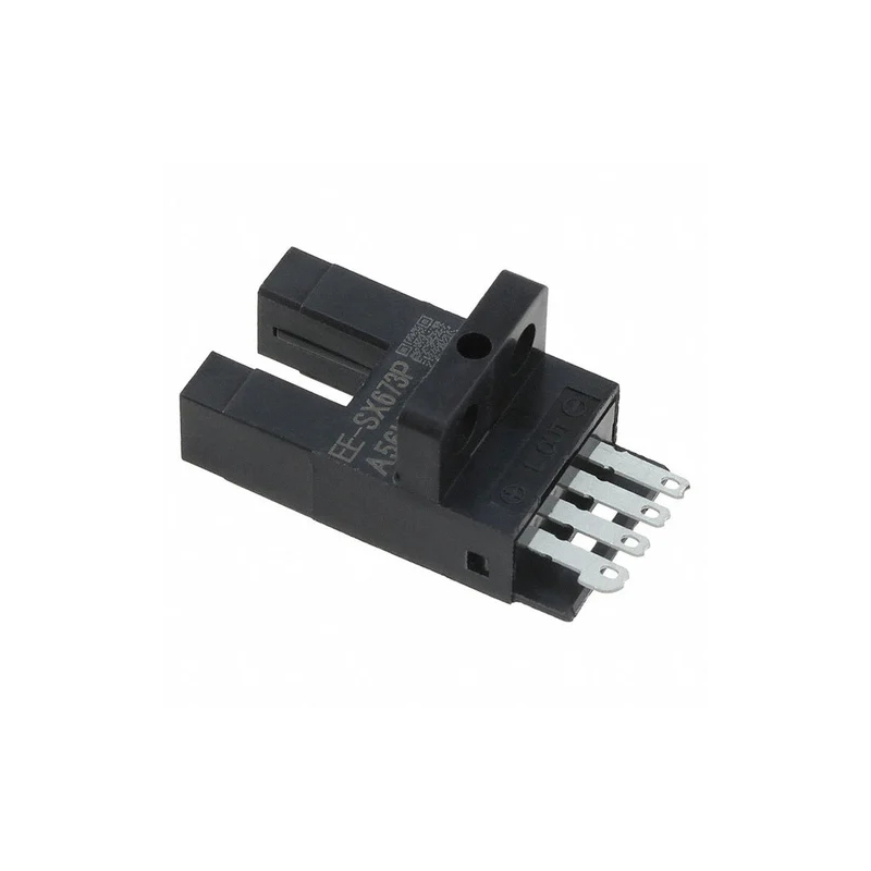
4. Thru-Hole (Slot) Sensors: The Miniature Interrupters
- Working Mechanism:
-
- A compact unit with an internal emitter-receiver pair separated by a slot (e.g., 2mm to 50mm gap).
-
- Any object passing through the slot blocks the direct beam, triggering an output.
- Key Advantage: Extremely fast and precise, ideal for detecting small, fast-moving objects (e.g., paper in a printer or tiny components on an assembly line).
- Real-World Example: In a ticket validator, a thru-hole sensor detects if a ticket is properly inserted by checking if it blocks the slot’s beam—ensuring no 卡纸 (paper jams).
5. Fiber-Optic Sensors: The Flexible Pathfinders
- Working Mechanism:
-
- A separate sensor head (emitter/receiver) connects to a fiber-optic probe via flexible cables.
-
- Light travels through the fiber to the probe, which emits it toward the target. Reflected light returns through the fiber to the receiver.
- Key Advantage: Can navigate tight spaces or harsh environments (high heat, moisture) where traditional sensors can’t fit. The probe can be shaped (e.g., right-angle, micro-tip) for unique mounting needs.
- Real-World Example: In semiconductor manufacturing, a fiber-optic sensor with a tiny probe detects microchips on a conveyor, even in the confined space of a cleanroom.
Signal Processing: From Raw Data to Actionable Output
1. Analog vs. Digital Outputs
- Analog Sensors: Provide a continuous voltage/current signal (e.g., 0-10V, 4-20mA) proportional to the detected light intensity, allowing precise distance measurement (e.g., determining how close a robot arm is to an object).
- Digital Sensors: Output a binary signal (ON/OFF) when the light level crosses a threshold, ideal for presence/absence detection (e.g., triggering a conveyor belt to start when a package is detected).
2. Noise Filtering and Modulation
To ensure reliable signals:
- Frequency Modulation: As mentioned, emitting pulsed light at a specific frequency (e.g., 50kHz) lets the receiver ignore constant ambient light.
- Time Delays: Some sensors include a short delay before triggering an output, ignoring brief light fluctuations (e.g., from passing shadows) to prevent false positives.
- Hysteresis: A built-in margin that requires the light level to rise/fall significantly above/below the threshold before switching states, reducing chatter from borderline detections.
Real-World Operation: How Sensors Adapt to Challenges
1. Overcoming Ambient Light Interference
- Problem: Sunlight or bright LEDs can flood the receiver with light, masking the sensor’s own beam.
- Solution:
-
- Use infrared emitters (invisible to ambient light sources) with wavelength filters on the receiver.
-
- Increase modulation frequency and signal amplitude, making the sensor’s beam "louder" than background light.
2. Handling Dust and Contamination
- Problem: Dirt on the emitter/receiver lens or retroreflective target reduces light transmission.
- Solution:
-
- Sensors in dusty environments often have protective covers or self-cleaning mechanisms (e.g., air blowers).
-
- Regular maintenance schedules to clean lenses and targets, ensuring optimal light path.
3. Detecting Difficult Objects
- Transparent Objects: Use infrared through-beam sensors, as IR light passes through plastic/glass but reflects off edges.
- Shiny Objects (Specular Reflection): In diffuse mode, angle the sensor slightly so the receiver captures scattered light instead of direct reflection.
- Dark Objects: Increase emitter power or switch to a through-beam configuration, where reflection isn’t needed.
Choosing the Right Working Mechanism for Your Needs
When selecting a photoelectric sensor based on its operational principles:
- Range Requirements:
-
- Long range (10m+): Through-beam (laser) or retroreflective with high-efficiency targets.
-
- Short range (0-2m): Diffuse or thru-hole sensors.
- Target Properties:
-
- Color/Texture: Through-beam for any color; diffuse for consistent surfaces (adjust sensitivity for dark/light objects).
-
- Size/Shape: Laser-based through-beam or fiber-optic for tiny objects; wide-beam LED diffuse for large items.
- Environment:
-
- Harsh conditions: Fiber-optic or sealed IP67-rated sensors.
-
- Noisy light: Modulated infrared sensors with high-frequency emission.
- Output Needs:
-
- Simple detection: Digital output (PNP/NPN).
-
- Precision measurement: Analog output or sensors with IO-Link for continuous data.
Conclusion: The Mechanical Poetry of Light and Logic
Photoelectric sensors are a testament to how simple physical principles—light emission, reflection, and detection—can be engineered into highly sophisticated devices. Their ability to convert light behavior into actionable signals relies on a delicate balance of component design, wavelength selection, and signal processing, adapted to countless real-world scenarios.
By understanding how they work—from the emitter projecting a modulated beam to the receiver translating scattered light into an electrical signal—you gain the knowledge to select, install, and troubleshoot these sensors effectively. Whether you’re automating a factory, building a smart device, or simply curious about the technology around you, the inner workings of photoelectric sensors reveal a world where light itself becomes a tool for precision, efficiency, and innovation.
As technology advances, expect these "optical eyes" to grow smarter—with self-calibrating sensors, adaptive modulation, and integration with AI for predictive maintenance. But at their core, their magic remains in the fundamental interplay of light and logic, proving that even the simplest physical phenomena can drive the most complex modern systems.
What is the Difference Between Brushed and Brushless Motors
How to Adjust Stepper Motor Current
Related Article

Brushless DC (BLDC) motors are widely used in EVs, drones, industrial machinery, and robotics for their efficiency and long lifespan. Unlike brushed motors—where reversing direction only requires swapping power leads—BLDC motors rely on electronic commutation, making direction reversal more nuanced.
How to Reverse Direction in Brushless Motors
Brushed and brushless DC motors are two of the most common electric motor designs, powering everything from toys to electric vehicles. While both convert electrical energy to mechanical motion, their internal structures, performance, and use cases differ drastically.
What’s the Difference Between a Brushed and Brushless Motor
Brushed DC motors are reliable, but wear and tear over time can lead to failure. Whether you’re troubleshooting a power tool, household appliance, or industrial conveyor motor, knowing the signs of a bad brushed motor saves time and prevents further damage.
How to Know If a Brushed Motor Is Bad
