


How Does a Solenoid Valve Work
2025-07-26
How Does a Solenoid Valve Work?
Solenoid valves are ubiquitous in modern engineering, quietly regulating fluid flow in everything from household appliances to industrial machinery. But beneath their seemingly simple function lies a sophisticated interplay of electricity, magnetism, and mechanics. Understanding how these devices convert electrical signals into precise fluid control requires diving into their operational sequence, component interactions, and the variables that shape their performance. This blog breaks down the inner workings of solenoid valves, exploring the process step by step, examining design variations, and highlighting real-world dynamics.
From Electricity to Motion: The Core Energy Conversion
At its heart, a solenoid valve is an energy converter, transforming electrical energy into mechanical motion to control fluid flow. This conversion happens in three distinct phases, each depend on the previous to achieve seamless operation.
The Electrical Trigger: Energizing the Coil
The process begins with an electrical current—either alternating current (AC) or direct current (DC)—flowing through the solenoid coil. This coil, typically made of copper wire wound around a ferromagnetic core (such as iron), acts as an electromagnet. When current passes through the coil, it generates a magnetic field with strength proportional to the current magnitude and the number of wire turns. For example, a 12V DC coil with 1,000 turns might produce a magnetic flux density of 0.5 tesla, while a 24V DC coil with 2,000 turns could reach 1 tesla under the same current.
This magnetic field is critical: it creates the force needed to overcome mechanical resistance (like spring tension) and initiate movement. The coil’s design—including wire gauge and insulation—dictates its electrical characteristics, such as resistance (typically 50-500 ohms for DC coils) and power consumption (1-50 watts), which in turn influence the speed and force of the magnetic response.
Magnetic Force: Overcoming Mechanical Resistance
Once the magnetic field is established, it exerts a pulling force on the plunger (or armature), a movable ferromagnetic component positioned within or near the coil. The force magnitude depends on the magnetic field strength and the plunger’s material—high-permeability materials like annealed iron enhance attraction. For direct-acting valves, this force must be strong enough to overcome the spring’s preload (usually 0.5-5 newtons) and any fluid pressure acting on the seal.
In mathematical terms, the force (F) exerted by the magnetic field follows Coulomb’s law for magnetism, varying with the square of the magnetic flux density (B) and the plunger’s cross-sectional area (A): F ∝ B²A. This relationship explains why larger plungers or stronger magnetic fields are needed for high-pressure applications—they generate greater force to counteract fluid pressure.
Mechanical Motion: Opening or Closing the Flow Path
As the plunger is drawn toward the coil, it drives the attached seal (or plug) into motion, either opening or closing the valve’s orifice. In normally closed (NC) valves, the spring holds the seal against the orifice in the de-energized state; energizing the coil lifts the seal, allowing fluid to flow. In normally open (NO) valves, the spring keeps the seal retracted, and energization pushes it against the orifice, blocking flow.
This motion is precise, with travel distances typically ranging from 0.5mm to 5mm, depending on valve size. The speed of this movement—response time—varies by design: direct-acting valves actuate in 5-50 milliseconds, while pilot-operated valves may take 50-200 milliseconds due to fluid pressure dynamics.
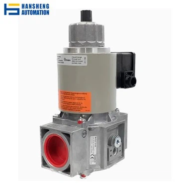
The De-Energization Cycle: Returning to Rest
When the electrical current is 切断,the magnetic field collapses, and the spring’s stored energy drives the plunger back to its original position. This resets the valve to its default state, closing or opening the flow path. The spring’s stiffness (measured in newtons per millimeter) determines how quickly the valve returns—stiffer springs (5-20 N/mm) result in faster reset times but require stronger magnetic forces to overcome during energization.
In some designs, a damper or cushioning mechanism slows the plunger’s return to reduce wear and noise, particularly in high-cycle applications like automated packaging machines, where valves may actuate thousands of times daily.
Core Components: How Each Part Enables Function
The Solenoid Coil: The Energy Transducer
The coil is the valve’s “power source,” converting electrical energy into magnetic energy. Its construction details—wire gauge (typically 22-30 AWG), number of turns (1,000-10,000), and insulation class (Class B for 130°C, Class F for 155°C)—dictate performance. For example, a 24V DC coil with 5,000 turns of 28 AWG wire might have a resistance of 200 ohms, drawing 120mA and consuming 2.88 watts. High-temperature coils (Class H, 180°C) use silicone insulation, suitable for steam applications, while automotive coils often feature epoxy potting to resist vibration.
The Plunger: The Motion Transmitter
The plunger’s design balances magnetic responsiveness and mechanical precision. It may be solid (for strength) or hollow (to reduce weight and improve response time) and is often plated with nickel or chrome to resist corrosion. In pilot-operated valves, the plunger controls a small pilot orifice rather than the main seal, leveraging fluid pressure to amplify motion—this allows smaller coils to operate larger valves.
The Valve Body: Directing Fluid Flow
The valve body houses the orifice, fluid ports, and internal channels, guiding flow once the seal moves. Its geometry—including orifice diameter (0.5mm to 100mm), port size (1/32-inch to 12-inch), and flow path design—dictates flow rate (measured by Cv value, 0.1 to 100+). For laminar flow in precision systems (e.g., medical infusion pumps), the body’s internal surfaces are polished to Ra < 0.8μm to prevent turbulence, while industrial valves may have rugged, cast iron bodies for durability.
The Seal: Ensuring Leak-Free Operation
The seal is critical for preventing unwanted leakage, with materials chosen for compatibility with the fluid and operating conditions. Elastomeric seals (EPDM, Viton) compress to form a tight seal, ideal for low-to-medium pressures, while metal seals (brass, stainless steel) withstand high temperatures (up to 450°C) and pressures (1,000+ psi) in steam or hydraulic systems. The seal’s shape—flat, conical, or O-ring—optimizes contact with the orifice, with conical designs providing better sealing under varying pressures.
The Spring: Resetting the Mechanism
Springs are engineered for specific force and fatigue resistance. Made from music wire (carbon steel) or stainless steel (for corrosion resistance), they undergo heat treatment to maintain tension over millions of cycles. In proportional valves, the spring’s linearity ensures that flow rate varies predictably with electrical input—non-linear springs would cause inconsistent control, a critical flaw in applications like fuel injection.
Design Variations: How Different Solenoid Valves Work
Direct-Acting Valves: Simplicity in Motion
Direct-acting valves rely solely on the plunger’s motion to open/close the orifice, with no reliance on fluid pressure. This makes them suitable for low-pressure (0-150 psi) or vacuum applications, as they operate without minimum pressure. Their simplicity—fewer moving parts—results in fast response times (5-50ms) but limits size: most have ports ≤ 1/2-inch. In analytical instruments, for example, a 1/8-inch direct-acting valve with a 6V DC coil precisely controls reagent flow, opening in 10ms to deliver microliter volumes.
Pilot-Operated Valves: Harnessing Fluid Pressure
Pilot-operated valves use a two-stage process: the coil opens a small pilot orifice, relieving pressure in a chamber above a diaphragm/piston. The resulting pressure differential (between inlet and chamber) pushes the diaphragm upward, opening the main orifice. This design reduces the coil’s required force, allowing larger valves (1-inch to 4-inch ports) to handle high pressures (up to 1,000 psi). However, they require minimum inlet pressure (5-10 psi) to function—below this, the pressure differential is insufficient to open the main valve. In irrigation systems, 2-inch pilot-operated valves use this principle to control large water flows with small 24V AC coils.
Proportional Valves: Modulating Flow Continuously
Proportional valves adjust flow rate incrementally by varying the coil’s current, which changes the plunger’s position and thus the orifice opening. This requires precise magnetic force control—achieved via PWM (pulse-width modulation) or analog current signals (4-20mA)—and feedback mechanisms (e.g., Hall-effect sensors) to ensure position accuracy. For example, in automotive transmission control, a proportional valve modulates hydraulic pressure from 50 to 500 psi by varying current from 0.5A to 2.5A, with flow rate changing linearly (±2% error) to match engine demand.
Multi-Port Valves: Redirecting Flow Paths
Multi-port valves (3-way, 4-way) use a rotating or sliding spool (connected to the plunger) to redirect flow between ports. A 3-way valve might switch flow from an inlet to either of two outlets, while a 4-way valve reverses flow direction in a hydraulic cylinder (extending/retracting). The spool’s lands (cylindrical sections) seal unused ports, with precise machining (tolerances ≤ 0.01mm) ensuring no cross-port leakage. In pneumatic robotics, a 4-way valve with a 12V DC coil rapidly switches air flow to actuate grippers, with spool movement of 3mm changing flow direction in 30ms.
Key Variables That Influence Operation
Electrical Input: Voltage, Current, and Waveform
The coil’s performance depends on the electrical input: AC coils use alternating current (120V, 240V) and often include a shading ring to reduce humming (caused by magnetic field fluctuations), while DC coils (12V, 24V) require rectification but offer quieter operation. Current stability is critical—fluctuations of ±10% can alter magnetic force, affecting response time. For example, a 24V DC coil rated at 1A (24W) may experience a 20% reduction in force if voltage drops to 20V, potentially failing to open under high fluid pressure.
Fluid Properties: Pressure, Viscosity, and Chemistry
Fluid pressure opposes the plunger’s motion, with higher pressures requiring stronger magnetic forces. Viscous fluids (e.g., oils, slurries) create more resistance than low-viscosity fluids (water, air), slowing valve actuation—this is why pilot-operated valves, which use fluid pressure to assist motion, are preferred for viscous media. Chemical compatibility is also key: aggressive fluids (acids, solvents) require PTFE bodies and seals, while abrasive slurries need hardened steel components to prevent wear.
Temperature: Affecting Materials and Performance
High temperatures (above 100°C) soften elastomeric seals, reducing their effectiveness, while low temperatures (-40°C) make them brittle. Magnetic materials also lose permeability at high temperatures—above 150°C, iron’s permeability decreases, weakening the coil’s force. This is why high-temperature valves use metal seals and heat-resistant coil insulation (e.g., Class H for 180°C) and may include cooling fins to dissipate heat.
Mechanical Wear: Degrading Performance Over Time
Friction between the plunger and guide, or seal wear from repeated contact with the orifice, increases response time and leakage. For example, a valve with a worn seal may develop a leakage rate of 0.1 cc/min after 1 million cycles, up from 0.01 cc/min initially. Regular maintenance—lubricating moving parts, replacing seals—extends life, with industrial valves often lasting 10+ million cycles under proper conditions.
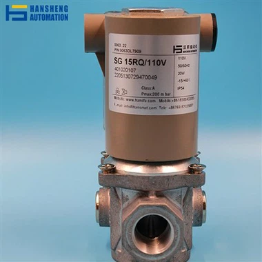
Real-World Operation: How Solenoid Valves Work in Practice
In Automotive Fuel Injection: Precision Timing
In gasoline engines, solenoid valves (injectors) open for 2-10 milliseconds to spray fuel into cylinders, with timing synchronized to the engine’s rotation. The coil (12V DC, 10-15 ohms) energizes, lifting a plunger that opens the injector nozzle. Fuel pressure (30-100 psi) atomizes the fuel, with flow rate varying by injector size (Cv 0.5-2.0). Proportional control adjusts open time based on sensor inputs—more fuel is injected under heavy load, less at idle—optimizing combustion efficiency.
In Industrial Pneumatic Systems: Controlling Actuators
A 3-way solenoid valve in a factory robot’s gripper circuit works as follows: de-energized, it vents air from the gripper, keeping it open; energized (24V DC), it directs compressed air (80-100 psi) into the gripper, closing it. The valve’s fast response (20ms) ensures the gripper operates in sync with the robot’s arm, handling 50+ cycles per minute without lag. Pilot-operated versions with 1-inch ports control larger actuators, using 5 psi pilot pressure to switch 100 psi main air flow.
In Medical Ventilators: Regulating Oxygen Flow
A miniature direct-acting valve (1/16-inch port) controls oxygen flow in ventilators, opening in 8ms to deliver precise volumes (50-1,000 mL) to patients. The coil (5V DC, 0.5W) generates minimal heat to avoid affecting oxygen temperature, while a silicone seal ensures zero leakage—critical for patient safety. The valve’s response time is synchronized with the ventilator’s microcontroller, which adjusts open duration to match the patient’s breathing rate (10-30 breaths per minute).
In Irrigation Systems: Managing Water Distribution
A 2-inch pilot-operated valve controls a farm’s irrigation zone. De-energized, spring pressure keeps it closed; when the controller sends 24V AC to the coil, the pilot orifice opens, relieving pressure above the diaphragm. Water pressure (30 psi) pushes the diaphragm up, opening the main orifice to deliver 50+ gallons per minute. The valve’s minimum pressure requirement (5 psi) ensures it works even with low water pressure, while a manual override allows operation during power outages.
Conclusion
A solenoid valve’s operation is a masterclass in energy conversion—transforming electricity into magnetism, then into mechanical motion, all to regulate fluid flow with precision. Its functionality depends on the seamless interaction of components: the coil generating force, the plunger transmitting motion, the seal controlling flow, and the spring resetting the system. Design variations—direct-acting, pilot-operated, proportional—adapt this core mechanism to diverse needs, from microscale medical devices to industrial pipelines.
Understanding how a solenoid valve works requires appreciating not just individual parts, but their dynamic interplay with electrical inputs, fluid properties, and environmental conditions. Whether opening for milliseconds to inject fuel or maintaining pressure in a water system, these devices exemplify the power of electromechanical engineering to enable automation, efficiency, and control in countless applications.
What Is a Variable Valve Timing Solenoid
What Is a Solenoid Valve
Related Article

Brushless DC (BLDC) motors are widely used in EVs, drones, industrial machinery, and robotics for their efficiency and long lifespan. Unlike brushed motors—where reversing direction only requires swapping power leads—BLDC motors rely on electronic commutation, making direction reversal more nuanced.
How to Reverse Direction in Brushless Motors
Brushed and brushless DC motors are two of the most common electric motor designs, powering everything from toys to electric vehicles. While both convert electrical energy to mechanical motion, their internal structures, performance, and use cases differ drastically.
What’s the Difference Between a Brushed and Brushless Motor
Brushed DC motors are reliable, but wear and tear over time can lead to failure. Whether you’re troubleshooting a power tool, household appliance, or industrial conveyor motor, knowing the signs of a bad brushed motor saves time and prevents further damage.
How to Know If a Brushed Motor Is Bad
