


How Does a Stepper Motor Work
2025-06-26
How Does a Stepper Motor Work? A Detailed Guide to Operation and Control
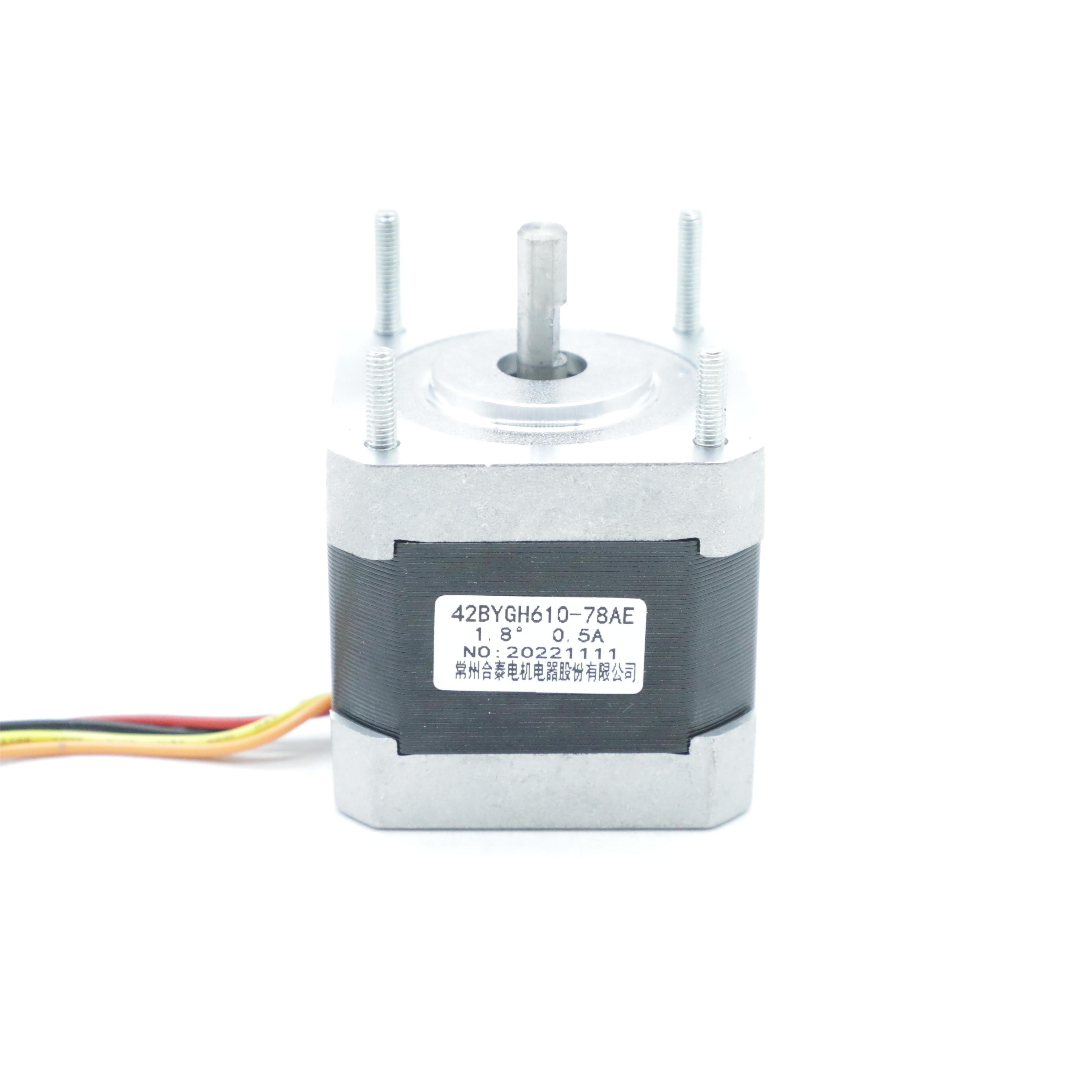
Stepper motors are precision motion devices that convert electrical pulses into controlled mechanical rotations. Unlike traditional motors that spin continuously, they move in discrete steps, making them essential for applications requiring accurate positioning, such as 3D printers, CNC machines, and robotics. In this guide, we’ll unpack the inner workings of stepper motors, exploring their mechanical structure, electromagnetic principles, stepping mechanisms, and control systems—providing a technical yet accessible explanation of their operation.
1. Core Mechanical Structure: Stator and Rotor Interaction
1.1 Stator: The Magnetic Field Generator
The stator is the stationary outer part of the motor, containing electromagnetic windings organized into phases (e.g., 2-phase, 3-phase, or 5-phase). Each phase consists of coils wrapped around stator poles, which generate magnetic fields when energized by a driver circuit. For a 2-phase motor:
- Phase A and Phase B windings are opposite each other on the stator.
- Each phase can be energized with current in two directions (bipolar) or one direction (unipolar), creating north/south magnetic poles.
1.2 Rotor: The Movable Magnetic Element
The rotor is the inner rotating shaft, designed in one of three configurations:
- Permanent Magnet (PM) Rotor: Contains a radial permanent magnet with alternating north/south poles (e.g., 2-pole or 4-pole).
- Reaction (Variable Reluctance, VR) Rotor: Made of soft magnetic material (iron) with evenly spaced teeth (no permanent magnet).
- Hybrid Rotor: Combines a permanent magnet (axial magnetization) with soft magnetic teeth for high torque and precision.
The rotor’s design directly impacts step angle, torque, and speed—with hybrid rotors being the most common for their balance of performance.
2. Electromagnetic Principles: How Pulses Create Motion
2.1 The Basic Law of Magnetic Attraction
Stepper motor motion relies on one simple principle: opposite magnetic poles attract, like poles repel. When a stator phase is energized:
- It creates a magnetic field at the corresponding stator poles.
- The rotor’s magnetic poles (or teeth, in VR/hybrid motors) align with the nearest stator poles to minimize magnetic reluctance (the "path of least resistance" for magnetic flux).
2.2 Step Generation: Sequential Phase Energization
To create rotation, stator phases are energized in a specific sequence, causing the rotor to "step" from one position to the next:
Example: 2-Phase Bipolar Motor (1.8° Step Angle)
- Phase A+ (Positive Current): North pole at Phase A, south at Phase A- (opposite side).
- Rotor aligns with Phase A poles.
- Phase B+ Activated, Phase A+ Deactivated: Rotor shifts to align with Phase B poles, moving 1.8°.
- Phase A- Activated (Reverse Current): North pole flips to Phase A-, rotor steps another 1.8°.
- Phase B- Activated: Completes the full-step sequence, creating 360° rotation over 200 steps.
This sequence is controlled by a stepper driver, which converts low-power signals from a microcontroller into the high-current pulses needed to energize the windings.
3. Stepping Modes: Full-Step, Half-Step, and Micro-Step
3.1 Full-Step Mode (Basic Operation)
- Energization: One or two phases are energized at a time (depending on motor type).
- Step Angle: Uses the motor’s native resolution (e.g., 1.8° for a 200-step/rev hybrid motor).
- Torque: Maximum torque when two phases are energized (bipolar motors), as both poles pull the rotor.
- Example Sequence (2-Phase Bipolar): A+ → B+ → A- → B- → A+ (repeats).
3.2 Half-Step Mode (Increased Resolution)
- Energization: Alternates between single-phase and two-phase energization.
- Step Angle: Half the native step angle (e.g., 0.9° for the same motor), doubling resolution.
- Sequence: A+ → A+B+ → B+ → B+A- → A- → A-B- → B- → B-A+ → A+ (repeats).
- Advantage: Smoother motion than full-step, though torque decreases slightly when single-phase is energized.
3.3 Micro-Step Mode (Ultra-Fine Control)
- Principle: Uses current regulation to partially energize phases, creating sub-steps (e.g., 1/16 or 1/32 of the native step).
- How it works:
-
- A driver applies a fraction of the rated current to each phase (e.g., 62.5% to Phase A and 37.5% to Phase B).
-
- The resulting combined magnetic field pulls the rotor to an intermediate position between full steps.
- Advantages:
-
- Extremely fine resolution (e.g., 0.1125° per micro-step for 1/16 micro-stepping on a 1.8° motor).
-
- Reduced vibration and noise at low speeds.
- Requirement: Drivers with digital signal processing (DSP) or analog current control for precise phase current adjustment.
4. Control Systems: From Pulses to Motion
4.1 The Role of Stepper Drivers
A stepper driver is essential for translating low-power control signals into motor-compatible current:
- H-Bridge Circuits: For bipolar motors, allow current reversal in each phase (enabling direction control).
- Current Limiting: Prevents overheating by regulating phase current to the motor’s rated value.
- Pulse Generation: Accepts input signals (STEP and DIRECTION) from a microcontroller:
-
- STEP Signal: Each pulse triggers one step (frequency determines speed: higher frequency = faster rotation).
-
- DIRECTION Signal: High/low voltage sets rotation direction (e.g., clockwise vs. counterclockwise).
4.2 Microcontroller Integration (Example: Arduino)
Controlling a stepper motor with a microcontroller involves:
- Defining pin connections for STEP, DIRECTION, and enable signals.
- Sending STEP pulses at a specific frequency (e.g., 1000 pulses per second for 5 RPM on a 200-step motor).
- Adjusting pulse frequency to control speed (using timer interrupts for precise timing).
// Simplified Arduino Code for 2-Phase Stepper const int stepPin = 8; const int dirPin = 9; void setup() { pinMode(stepPin, OUTPUT); pinMode(dirPin, OUTPUT); digitalWrite(dirPin, HIGH); // Set direction } void loop() { for (int i = 0; i < 200; i++) { // 1 full revolution digitalWrite(stepPin, HIGH); delay(1); // Adjust delay for speed digitalWrite(stepPin, LOW); delay(1); } } 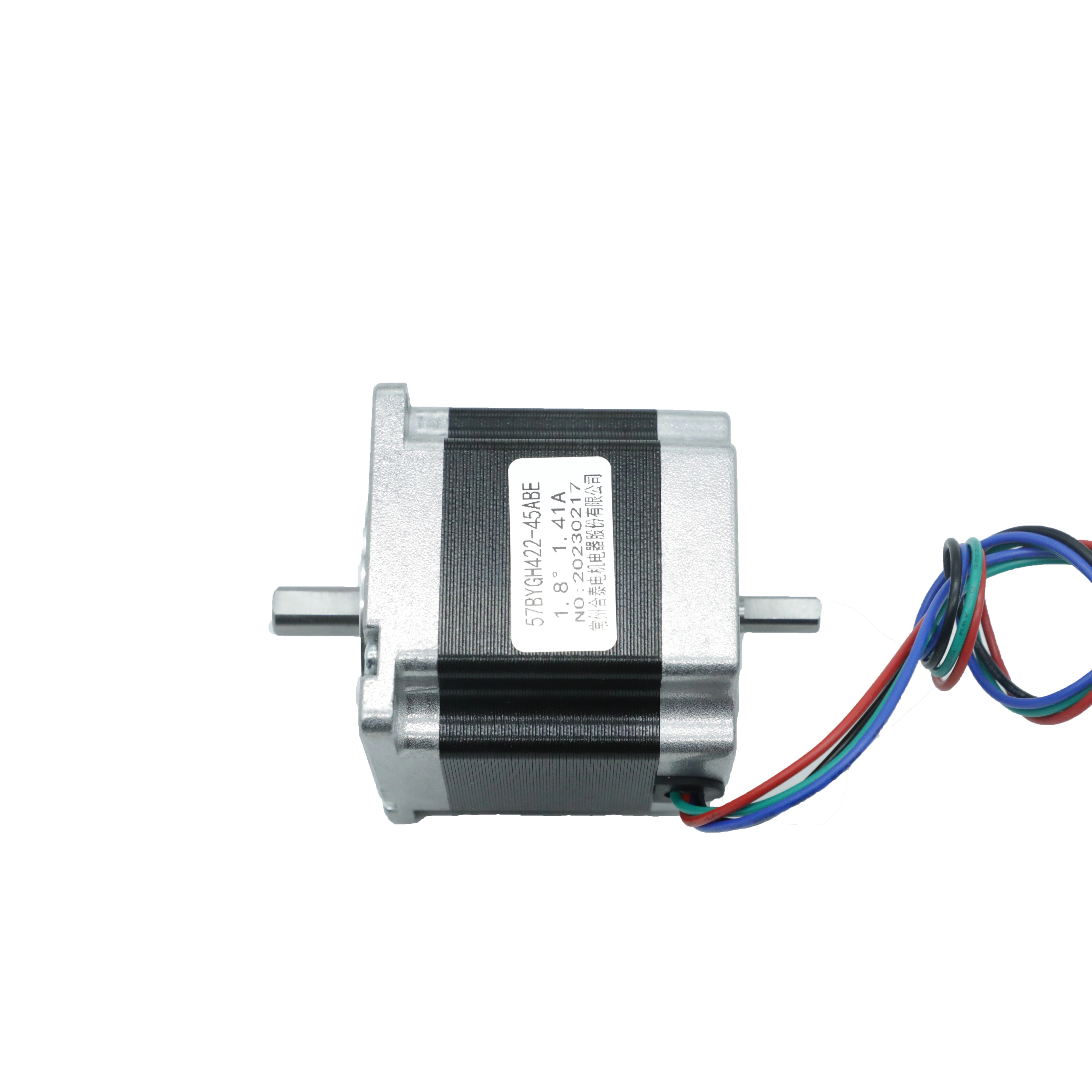
4.3 Advanced Control: Closed-Loop Systems
While most stepper applications use open-loop control (no feedback), high-precision systems may add:
- Encoders: To detect actual position and correct for missed steps (common in industrial robotics).
- PID Controllers: To maintain speed stability under varying loads by adjusting pulse frequency in real time.
5. Torque-Speed Characteristics: Why Steppers Behave Differently
5.1 Torque at Low Speeds
- Holding Torque: The maximum static torque when the motor is stationary and energized.
- Dynamic Torque: Decreases as speed increases due to two factors:
-
- Inductive Reactance: Higher speeds mean faster current changes, causing voltage drops in windings (XL = 2πfL).
-
- Rotor Inertia: At high speeds, the rotor can’t keep up with rapid phase changes, leading to missed steps.
5.2 Speed Limitations
- Pull-In Speed: The maximum speed at which the motor can start without missing steps.
- Pull-Out Speed: The maximum speed under load before losing synchronization.
- Mitigation: Micro-stepping and proper driver tuning can extend usable speed ranges.
6. Common Challenges and Solutions
6.1 Missed Steps
- Cause: Inadequate current, too fast pulse frequency, or excessive load torque.
- Solution: Increase driver current, reduce speed, or choose a higher-torque motor.
6.2 Vibration and Noise
- Cause: Resonance at specific step frequencies (e.g., full-step operation at low speeds).
- Solution: Switch to half-step or micro-step mode; add mechanical dampers or use higher-quality bearings.
6.3 Overheating
- Cause: Excessive current, poor ventilation, or continuous operation at max torque.
- Solution: Use current-limited drivers, add heat sinks, or enable idle current reduction (sleep mode).
7. How Steppers Differ from Other Motors
|
Feature
|
Stepper Motor
|
Servo Motor
|
DC Motor
|
|
Position Control
|
Open-loop (steps via pulses)
|
Closed-loop (feedback + PID)
|
Continuous (no precision)
|
|
Motion Type
|
Discrete steps (incremental)
|
Smooth rotation to any angle
|
Continuous rotation
|
|
Torque at Zero Speed
|
High (holding torque)
|
Low (needs feedback to hold)
|
None (stalls)
|
|
Control Complexity
|
Moderate (driver + pulse signals)
|
High (encoder + controller)
|
Low (voltage control)
|
8. Practical Applications of Stepper Operation
8.1 3D Printers
- X/Y/Z Axes: Steppers move the print head and build platform with micro-stepping for 0.01mm precision.
- Extruder Motor: Controls filament feed rate by stepping at a constant speed.
8.2 CNC Machines
- Precision Cutting: High-torque hybrid steppers with closed-loop feedback ensure accurate tool positioning, even under heavy loads.
8.3 Medical Devices
- Syringe Pumps: Micro-stepping allows microliter-level fluid dispensing by controlling the piston’s incremental movement.
Conclusion
Understanding how a stepper motor works requires grasping the interplay between electromagnetic fields, precise phase energization, and mechanical design. From the stator’s magnetic poles pulling the rotor’s teeth to the microcontroller generating step pulses, every component plays a role in translating electrical signals into controlled motion. Whether you’re using full-step for simple positioning or micro-stepping for ultra-precision, mastering these principles lets you leverage steppers’ unique advantages in accuracy, open-loop control, and torque consistency.
By pairing the right motor type with a well-tuned driver and control system, you can create reliable motion solutions for everything from DIY projects to industrial automation. Remember: the key to success lies in matching step angle, torque, and control mode to your application’s specific needs—turning the science of electromagnetism into practical, repeatable motion.
How to Control a Stepper Motor
What Is a Stepper Motor
Related Article

Brushless DC (BLDC) motors are widely used in EVs, drones, industrial machinery, and robotics for their efficiency and long lifespan. Unlike brushed motors—where reversing direction only requires swapping power leads—BLDC motors rely on electronic commutation, making direction reversal more nuanced.
How to Reverse Direction in Brushless Motors
Brushed and brushless DC motors are two of the most common electric motor designs, powering everything from toys to electric vehicles. While both convert electrical energy to mechanical motion, their internal structures, performance, and use cases differ drastically.
What’s the Difference Between a Brushed and Brushless Motor
Brushed DC motors are reliable, but wear and tear over time can lead to failure. Whether you’re troubleshooting a power tool, household appliance, or industrial conveyor motor, knowing the signs of a bad brushed motor saves time and prevents further damage.
How to Know If a Brushed Motor Is Bad
