


How to Adjust Stepper Motor Current
2025-07-02
How to Adjust Stepper Motor Current?
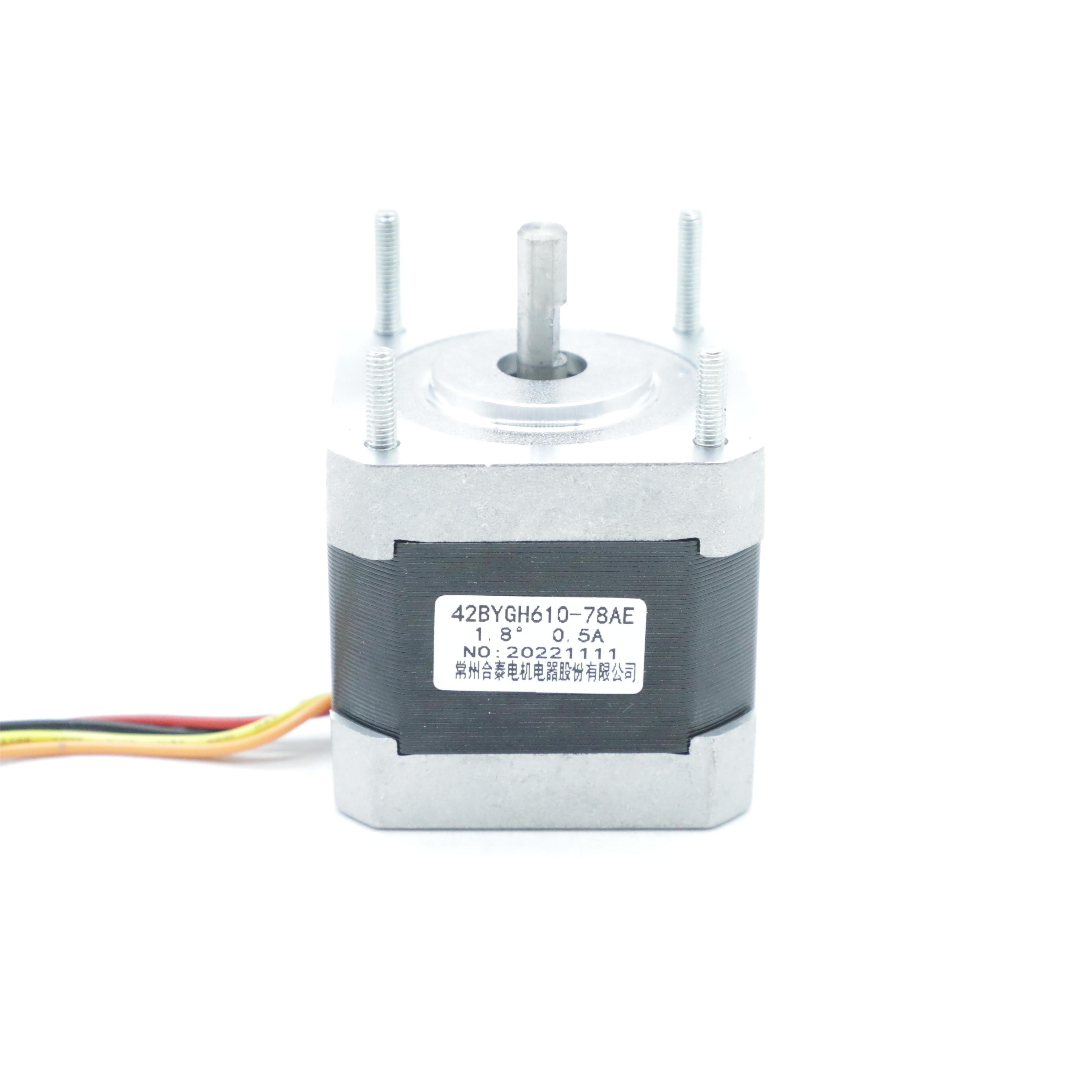
Stepper motors are widely used in precision motion control systems for their ability to convert electrical pulses into discrete mechanical movements. One critical factor influencing their performance, efficiency, and lifespan is the operating current. Properly adjusting the stepper motor current ensures optimal torque output, minimizes heat generation, and prevents damage from overcurrent or undercurrent. In this detailed guide, we’ll explore why current adjustment matters, the tools you need, and a step-by-step process to fine-tune this critical parameter.
1. Understanding Stepper Motor Current Basics
1.1 What Is Stepper Motor Current?
Stepper motors operate by energizing their stator windings in a specific sequence, creating magnetic fields that attract the rotor. The phase current (current flowing through each winding phase) determines the strength of these magnetic fields, directly impacting:
- Torque: Higher current increases torque but also heat.
- Heat Generation: Excessive current leads to overheating, reducing motor life and causing performance degradation.
- Noise and Vibration: Incorrect current settings can amplify mechanical vibrations and operational noise.
Key terms to know:
- Holding Current: The current maintained when the motor is stationary (locked in position).
- RMS Current: The root-mean-square current rating, specifying the continuous operating current the motor can handle without overheating.
- Peak Current: The maximum instantaneous current during step transitions, which should not exceed the motor’s rating.
1.2 Why Adjust Stepper Motor Current?
- Optimize Torque: Match the motor’s current to the load requirements for consistent performance.
- Prevent Overheating: Excessive current causes winding insulation breakdown and permanent magnet demagnetization.
- Extend Lifespan: Proper current settings reduce wear on bearings, windings, and drive electronics.
- Improve Stability: Correct current minimizes resonance and missed steps, especially at high speeds.
2. Tools and Equipment Required
Before adjusting the current, gather these essential tools:
2.1 Hardware Tools
- Digital Multimeter (DMM): To measure phase current (DC mode for analog drives, check drive specifications for AC vs. DC measurement).
- Oscilloscope (Optional): For advanced users to monitor current waveforms and identify spikes.
- Screwdriver Set: Small flathead or hex screwdrivers for adjusting potentiometers on analog drives.
- Thermometer: To check motor temperature during testing (ideal operating temp < 80°C for most motors).
2.2 Documentation and Software
- Motor Data Sheet: Contains rated phase current (e.g., 1.7A RMS), voltage, and resistance values.
- Drive Controller Manual: Provides instructions for current adjustment (digital vs. analog methods).
- Control Software (for Digital Drives): Tools like Trinamic’s TMCL-IDE or Arduino libraries for configuring digital drives via USB/serial.
3. Step-by-Step Current Adjustment Process
3.1 Prepare the System
- Power Off the System: Disconnect all power sources to avoid damaging the drive or motor.
- Locate the Drive Controller: Identify the stepper motor driver (e.g., standalone driver like TB6600, or integrated controller in 3D printers/CNC machines).
- Note Current Settings: For analog drives, observe the initial potentiometer position (mark it with a pen for reference). For digital drives, record current parameters in the software.
3.2 Adjust Current for Analog Drives
Most low-cost stepper drivers (e.g., A4988, DRV8825) use potentiometers to set current.
Step 1: Calculate Target Current
- Formula:
 , where:
 = Reference voltage from the drive’s voltage regulator (e.g., 3.3V or 5V).
 = Sense resistor value (marked on the driver board, e.g., 0.1Ω).
- Safety Note: Never exceed the motor’s rated RMS current (e.g., if the motor is rated for 1.5A, set
 ).
).
Step 2: Measure Current
- Connect the multimeter in series with the motor phase (consult drive manual for test points).
- Power on the system and enable the motor (send a "hold" signal to keep it stationary).
- Read the DC current value—this is the holding current.
Step 3: Adjust the Potentiometer
- Turn the potentiometer slowly clockwise (increase current) or counterclockwise (decrease).
- Re-measure the current after each adjustment, aiming for 80-90% of the motor’s rated current for continuous operation (leaves headroom for heat).
3.3 Adjust Current for Digital Drives
Digital drives (e.g., Trinamic TMC2209, Smoothieware-compatible controllers) offer precise software-based adjustment.
Step 1: Connect to the Drive
- Use a USB-to-serial adapter or built-in interface to connect the drive to a computer.
- Open the manufacturer’s configuration software (e.g., MKS TMC2209 Configuration Tool).
Step 2: Set Current Parameters
- Locate the "Current Settings" menu and input the motor’s rated RMS current.
- Configure hold current (e.g., 70% of running current to reduce heat during idle).
- Save settings and reboot the drive to apply changes.
3.4 Verify Adjustments
- Test Motor Operation: Run the motor through its full speed range, checking for smooth motion and absence of skipping steps.
- Monitor Temperature: After 10-15 minutes of operation, touch the motor—It should be warm (≤50°C) but not hot to the touch.
- Check for Noise/Vibration: Excessive humming or shaking indicates incorrect current (reduce current slightly if noisy).
4. Common Challenges and Troubleshooting
4.1 Current Too High: Symptoms and Fixes
- Symptoms: Motor overheats (≥80°C), driver thermal shutdown, burnt smell.
- Fixes:
-
- Reduce current by 10-20% and retest.
-
- Ensure proper ventilation/cooling for high-load applications.
-
- Check for mechanical binding (increased load requires higher current).
4.2 Current Too Low: Symptoms and Fixes
- Symptoms: Motor loses steps under load, weak holding torque, excessive vibration at low speeds.
- Fixes:
-
- Increase current in 5% increments until torque improves without overheating.
-
- Verify the sense resistor value and formula calculation for analog drives.
4.3 Inconsistent Current Readings
- Cause: Poor multimeter connection, AC current in unipolar drives, or noise in the circuit.
- Solution: Use a high-precision DMM, connect directly to the drive’s test points, and enable motor holding mode for stable measurement.
5. Best Practices for Long-Term Performance
5.1 Balance Current and Heat
- For continuous operation, set current to 80% of the motor’s rated RMS current (e.g., 1.2A for a 1.5A motor).
- Use current decay modes (e.g., slow decay, mixed decay) in drives to reduce eddy current losses.
5.2 Regular Maintenance
- Periodically check drive firmware/software for updates (improves current control algorithms).
- Clean dust and debris from motor windings to maintain heat dissipation.
5.3 Safety First
- Always power down before adjusting hardware (risk of electrostatic discharge or short circuits).
- Use insulated tools when working with high-voltage systems (e.g., industrial stepper setups).
6. Conclusion
Adjusting stepper motor current is a critical step in optimizing performance, reliability, and lifespan. By understanding your motor’s specifications, using the right tools, and following a systematic adjustment process, you can achieve precise control while avoiding common pitfalls like overheating and step loss. Whether working with analog potentiometers or advanced digital drives, the key is to balance torque requirements with thermal limits, ensuring your stepper system operates at its best in any application—from 3D printing to CNC machining and robotics.
By mastering current adjustment, you’ll unlock the full potential of your stepper motor, creating smoother motion, quieter operation, and a more durable mechanical system. Always refer to manufacturer documentation for specific drive and motor models, and don’t hesitate to test and iterate until you find the optimal settings for your unique setup.
How Does a Photoelectric Sensor Work
What Is a Stepper Motor Used For
Related Article

Brushless DC (BLDC) motors are widely used in EVs, drones, industrial machinery, and robotics for their efficiency and long lifespan. Unlike brushed motors—where reversing direction only requires swapping power leads—BLDC motors rely on electronic commutation, making direction reversal more nuanced.
How to Reverse Direction in Brushless Motors
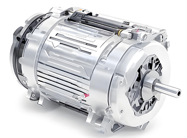
Brushed and brushless DC motors are two of the most common electric motor designs, powering everything from toys to electric vehicles. While both convert electrical energy to mechanical motion, their internal structures, performance, and use cases differ drastically.
What’s the Difference Between a Brushed and Brushless Motor
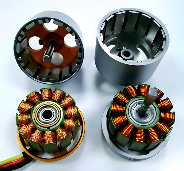
Brushed DC motors are reliable, but wear and tear over time can lead to failure. Whether you’re troubleshooting a power tool, household appliance, or industrial conveyor motor, knowing the signs of a bad brushed motor saves time and prevents further damage.
How to Know If a Brushed Motor Is Bad
