


How to Control a Servo Motor with a PLC
2025-07-17
How to Control a Servo Motor with a PLC?
Servo motors are the workhorses of precision motion control, powering everything from robotic arms to CNC machines. When paired with a Programmable Logic Controller (PLC), they become part of a flexible, reliable system that can execute complex movements with pinpoint accuracy. But how exactly do you control a servo motor with a PLC? This guide breaks down the process, from hardware setup to programming, ensuring you understand every step of integrating these two critical components.
Understanding the Basics: PLCs and Servo Motors
Before diving into control methods, let’s clarify the roles of each component:
What Is a PLC?
A PLC is an industrial computer designed to automate machinery and processes. It receives inputs (from sensors, buttons, or other devices), processes them according to a programmed logic, and sends outputs (to motors, valves, or alarms). PLCs excel in rugged environments, offering real-time responsiveness and easy scalability—key for industrial automation.
What Is a Servo Motor?
A servo motor is a closed-loop motor system that combines a motor, encoder, and controller (servo drive). Unlike regular motors, it uses feedback from the encoder to adjust its position, speed, or torque, ensuring it matches the desired setpoint. For example, if a CNC machine needs to move a tool to 35.2mm, the servo motor adjusts until the encoder confirms it has reached that exact position.
Why Pair PLCs with Servo Motors?
PLCs handle high-level logic (e.g., “start the conveyor when a part is detected”), while servo motors manage low-level motion (e.g., “move the arm 10cm at 500mm/s”). Together, they create systems that are:
- Accurate: Servos achieve positioning errors as low as ±0.01mm, guided by PLC commands.
- Flexible: PLC programs can be updated to change motion profiles without rewiring.
- Reliable: Industrial-grade components withstand vibration, dust, and temperature extremes.
Key Components for PLC-Servo Control
To control a servo motor with a PLC, you’ll need more than just the two devices. Here’s the essential hardware:
1. PLC with Motion Control Capabilities
Not all PLCs can control servos—look for models with:
- Pulse Outputs: To send step-and-direction signals (common in low-cost setups).
- Fieldbus Support: Protocols like EtherCAT, Modbus RTU, or Profibus for high-speed communication (critical for complex systems).
- Motion Instructions: Built-in programming blocks (e.g., “MC_MoveAbsolute” in IEC 61131-3 standards) to simplify motion control.
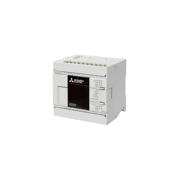
Popular choices include Siemens S7-1200 (for small systems), Allen-Bradley Micro800 (mid-range), and Mitsubishi FX5 (budget-friendly options).
2. Servo Drive
The servo drive acts as a bridge between the PLC and the motor. It converts the PLC’s command signals into electrical current to power the motor and uses encoder feedback to adjust performance. Drives must match the motor’s voltage (e.g., 24V DC for small servos, 400V AC for industrial models) and support the PLC’s communication protocol.
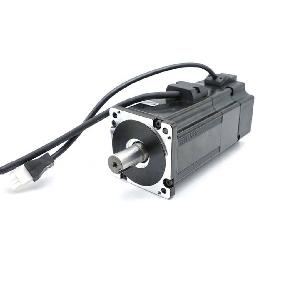
3. Servo Motor and Encoder
Choose a motor based on your load requirements:
- Torque: Measured in Nm (e.g., a 0.5Nm motor works for light robots; 5Nm+ for heavy machinery).
- Speed: Typically 3,000–6,000 RPM for industrial use.
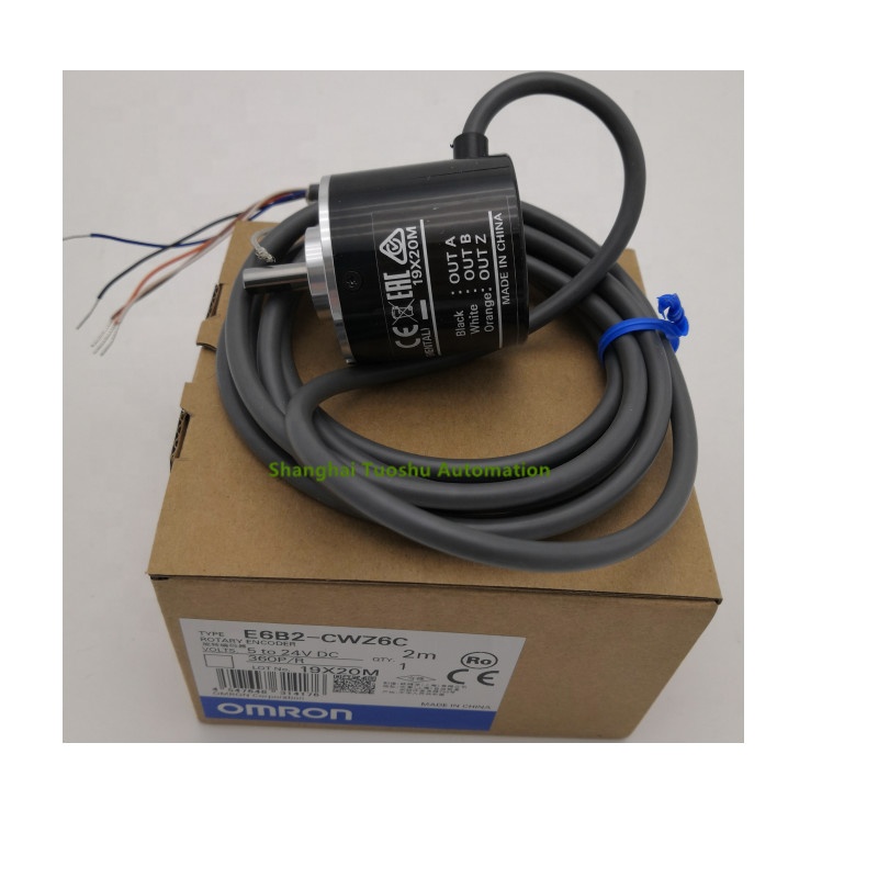
- Encoder Resolution: Higher counts per revolution (CPR) mean better accuracy. A 17-bit encoder (131,072 CPR) is standard for precision applications.
4. Wiring and Cabling
- Power Cables: Carry current from the drive to the motor (use shielded cables to reduce noise).
- Encoder Cables: Connect the encoder to the drive (twisted-pair, shielded cables prevent interference).
- Control Cables: Link the PLC to the drive (pulse wires for step-and-direction, or Ethernet/fieldbus cables for protocol-based control).
Methods to Control a Servo Motor with a PLC
PLCs communicate with servo drives using two primary methods, each suited to different applications:
Method 1: Pulse and Direction Signals (Step-and-Direction)
This is the simplest, most cost-effective method, ideal for basic positioning (e.g., moving a conveyor to a set point). Here’s how it works:
How It Functions
- The PLC sends two signals: pulse (a train of electrical pulses) and direction (a high/low voltage to indicate left/right or clockwise/counterclockwise).
- Each pulse corresponds to a tiny movement (e.g., 1 pulse = 0.01mm). The total number of pulses determines the distance.
- Pulse frequency controls speed: 10,000 pulses per second (Hz) might equal 500mm/s for a given motor.
Wiring Steps
- Connect the PLC’s pulse output (e.g., Y0 on Mitsubishi FX5) to the drive’s pulse input (PUL+).
- Connect the PLC’s direction output (e.g., Y1) to the drive’s direction input (DIR+).
- Connect the drive’s PUL- and DIR- to the PLC’s common ground (0V).
- Power the drive with the correct voltage (e.g., 24V DC for small drives) and connect the motor to the drive’s U/V/W terminals.
- Wire the encoder from the motor to the drive’s encoder inputs (A, B, Z signals).
Programming Basics
In ladder logic or structured text, use pulse-output instructions:
- Set Pulse Count: “PLS” (Pulse Output) 指令 in Mitsubishi PLCs, specifying the number of pulses (e.g., 50,000 for 50mm).
- Set Frequency: Define the speed (e.g., 20,000 Hz for 1m/s).
- Start/Stop: Use a trigger (like a sensor signal) to initiate the pulse train.
Example: To move a servo 100mm at 300mm/s:
- Calculate pulses: If 1 pulse = 0.002mm, 100mm requires 50,000 pulses.
- Calculate frequency: 300mm/s ÷ 0.002mm/pulse = 150,000 Hz.
Method 2: Fieldbus Communication (EtherCAT, Modbus, etc.)
For complex systems (e.g., multi-axis robots), fieldbus protocols enable high-speed, bidirectional communication between the PLC and servo drive. This method supports advanced features like torque control and real-time status feedback.
Common Protocols
- EtherCAT: Fast (100Mbps) and deterministic, ideal for synchronized multi-axis systems (e.g., 6-axis robots).
- Modbus RTU: Simple, low-cost, and widely supported—good for single-axis setups (e.g., packaging machines).
- Profibus DP: Used in older industrial systems, reliable for medium-speed applications.
How It Works
- The PLC sends commands (position, speed, torque) to the drive via the fieldbus.
- The drive returns real-time data (current position, error codes, temperature) to the PLC.
- Both devices use a shared data table (e.g., holding registers in Modbus) to exchange information.
Setup Steps
- Configure the PLC and drive with matching protocol settings (baud rate, node address, data format).
- Map drive parameters (e.g., “Target Position” = register 40001) to the PLC’s memory.
- Program the PLC to write to these registers (e.g., set register 40001 to 50000 for 50mm).
- Read drive status registers (e.g., register 40010) to confirm the motor has reached the target.
Programming Example (Modbus)
- Use “MODBUS_MASTER” 指令 in Siemens TIA Portal to send a write command to the drive’s target position register.
- Include error handling: If the drive returns an error code (e.g., “overload”), the PLC stops the motor and triggers an alarm.
Step-by-Step: Setting Up a PLC-Servo System
Let’s walk through a complete setup using the pulse-and-direction method for a simple conveyor positioning system:
1. Hardware Installation
- Mount the PLC, servo drive, and motor in a control cabinet, ensuring proper ventilation (drives generate heat).
- Connect the motor to the drive (U/V/W terminals) and the encoder to the drive’s encoder port.
- Wire the PLC’s pulse (Y0) and direction (Y1) outputs to the drive’s PUL+ and DIR+ inputs.
- Connect all ground wires to a common earth terminal to reduce noise.
2. Drive Configuration
Most servo drives require initial setup via software (e.g., Mitsubishi MR Configurator, Siemens Starter):
- Motor Parameters: Enter the motor’s rated current, encoder resolution, and maximum speed.
- Control Mode: Set to “Position Control” (for pulse signals) or “Velocity Control” (for speed commands).
- Acceleration/Deceleration: Define ramp rates (e.g., 1000mm/s²) to prevent sudden movements that stress the system.
3. PLC Programming
- Create Inputs: Map sensors (e.g., a photoelectric sensor at the start position) to PLC inputs (e.g., X0).
- Define Motion Logic: Use ladder logic to trigger the pulse train when the sensor detects a part.
X0 (Sensor) → [ ] → PLS Y0 (Pulse Output: 50,000 pulses, 20,000 Hz)- Add Safety Features: Include an emergency stop (X1) that halts the pulse train immediately.
4. Testing and Calibration
- Dry Run: Test without a load to verify the motor moves to the correct position.
- Calibrate: If the motor overshoots, adjust drive gains (proportional, integral) to improve response.
- Load Test: Run with the actual load to ensure the system handles torque requirements without slipping.
Troubleshooting Common PLC-Servo Issues
Even with careful setup, problems can arise. Here’s how to diagnose them:
1. Motor Doesn’t Move
- Check Power: Ensure the drive has 24V/400V and the motor is wired correctly (U/V/W not reversed).
- Check Signals: Use an oscilloscope to verify the PLC is sending pulses (look for a square wave at the drive’s PUL input).
- Drive Errors: Most drives have LEDs or displays showing errors (e.g., “E02” for overcurrent). Consult the manual to resolve.
2. Inaccurate Positioning
- Encoder Issues: A loose encoder cable can cause feedback errors. Check connections and replace damaged cables.
- Pulse Loss: Electrical noise may disrupt pulse signals. Add shielded cables or ferrite cores to reduce interference.
- Mechanical Backlash: Loose gears or belts introduce positioning errors. Tighten components or use anti-backlash hardware.
3. Motor Vibrates or Stalls
- Gain Settings: Too high a proportional gain causes oscillation; too low causes sluggishness. Adjust in the drive software.
- Overload: The motor may stall if the load exceeds its torque rating. Upgrade to a higher-torque motor or reduce acceleration.
Advanced Tips for Optimizing PLC-Servo Systems
- Use Absolute Encoders: These retain position data when powered off, avoiding the need to “home” the motor on startup.
- Synchronize Multi-Axis Movements: With EtherCAT, PLCs can coordinate multiple servos (e.g., a robot’s arm and gripper) to move in perfect harmony.
- Monitor Drive Data: Log drive temperatures, current, and error codes in the PLC to predict failures (e.g., a rising temperature may indicate a failing bearing).
- Backup Configurations: Save drive and PLC settings to a file—critical for quick recovery after a fault.
Conclusion
Controlling a servo motor with a PLC combines the precision of servos with the flexibility of PLC logic, creating systems that excel in industrial automation. Whether using pulse signals for simple positioning or fieldbus protocols for complex robots, the key is understanding how to integrate hardware, configure drives, and program the PLC to send accurate commands.
By following the steps outlined here—from selecting components to troubleshooting—you’ll be able to build reliable, high-performance systems that meet your application’s needs.
By following the steps outlined here—from selecting components to troubleshooting—you’ll be able to build reliable, high-performance systems that meet your application’s needs.
How to Control a Stepper Motor Using a PLC
How to Test a Proximity Sensor
Related Article

Brushless DC (BLDC) motors are widely used in EVs, drones, industrial machinery, and robotics for their efficiency and long lifespan. Unlike brushed motors—where reversing direction only requires swapping power leads—BLDC motors rely on electronic commutation, making direction reversal more nuanced.
How to Reverse Direction in Brushless Motors
Brushed and brushless DC motors are two of the most common electric motor designs, powering everything from toys to electric vehicles. While both convert electrical energy to mechanical motion, their internal structures, performance, and use cases differ drastically.
What’s the Difference Between a Brushed and Brushless Motor
Brushed DC motors are reliable, but wear and tear over time can lead to failure. Whether you’re troubleshooting a power tool, household appliance, or industrial conveyor motor, knowing the signs of a bad brushed motor saves time and prevents further damage.
How to Know If a Brushed Motor Is Bad
