


How to Control a Stepper Motor Using a PLC
2025-07-18
How to Control a Stepper Motor Using a PLC?
Stepper motors are indispensable in precision motion control applications, from 3D printers to automated assembly lines. Their ability to move in discrete, predictable steps makes them ideal for tasks requiring exact positioning—no guesswork, no slippage, just reliable movement. When paired with a Programmable Logic Controller (PLC), stepper motors become part of a robust automation system that can execute complex sequences with ease. This guide explains how to control a stepper motor using a PLC, covering everything from component selection to programming and troubleshooting.
Understanding Stepper Motors and PLCs: Key Differences from Servos
Before diving into control methods, it’s critical to distinguish stepper motors from servo motors—their differences shape how they interact with PLCs:
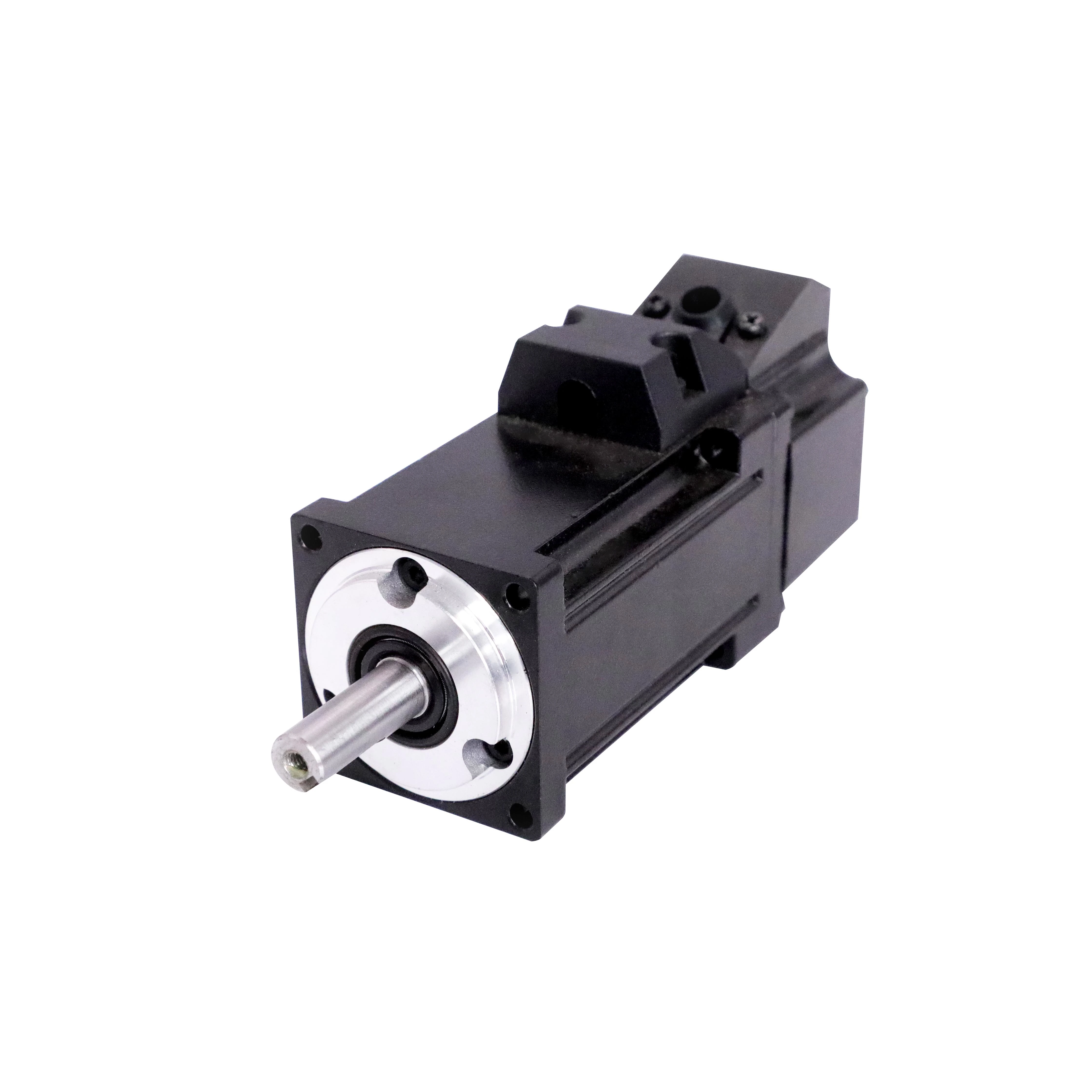
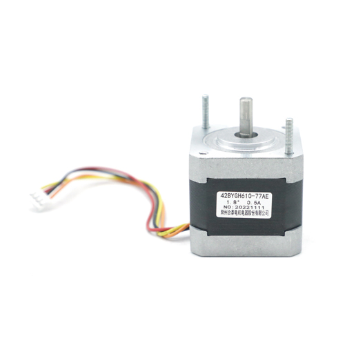
What Is a Stepper Motor?
A stepper motor converts electrical pulses into precise mechanical movement. It divides a full rotation (360°) into equal steps, with each step corresponding to a fixed angle (e.g., 1.8° per step for a common bipolar stepper). Unlike servo motors, steppers operate in open-loop control—they don’t use encoders for feedback. Instead, they rely on the PLC to send the exact number of pulses needed to reach a target position. This simplicity makes them cost-effective for applications where moderate precision (±0.5% error) is acceptable.
Why Use a PLC with a Stepper Motor?
PLCs excel at coordinating multiple devices and executing logic-based sequences. When paired with steppers, they:
- Control step count (position) and pulse frequency (speed) with high accuracy.
- Integrate with sensors to trigger movements (e.g., “move 50mm when a part is detected”).
- Handle complex sequences (e.g., “move forward 100mm, pause 2s, reverse 30mm”).
- Provide robust industrial communication (e.g., Modbus) for system integration.
Stepper vs. Servo: When to Choose Steppers
Steppers are preferred for:
- Low-to-medium speed applications (≤1000 RPM).
- Cost-sensitive setups (no encoder reduces expense).
- Simple positioning tasks (e.g., feeding paper in printers).
- Environments where vibration is acceptable (steppers can vibrate at low speeds).
Essential Components for Stepper Motor-PLC Control
To control a stepper motor with a PLC, you’ll need these core components, each playing a critical role in the system:
1. PLC with High-Speed Pulse Outputs
Not all PLCs can generate the fast, precise pulses steppers require. Look for models with:
- High-speed counters/pulse generators: Capable of outputting 100kHz+ pulses (e.g., Siemens S7-1214C has 4 high-speed outputs up to 100kHz).
- Pulse-direction support: Separate outputs for step pulses and direction signals.
- Programming flexibility: Built-in instructions for pulse control (e.g., “PULSE” in Allen-Bradley Logix5000).
Popular choices include:
- Entry-level: Mitsubishi FX5-16MT/ES (60kHz pulse outputs).
- Mid-range: Siemens S7-1200 (100kHz, supports PROFINET).
- Industrial: Allen-Bradley Micro850 (200kHz, compact design).
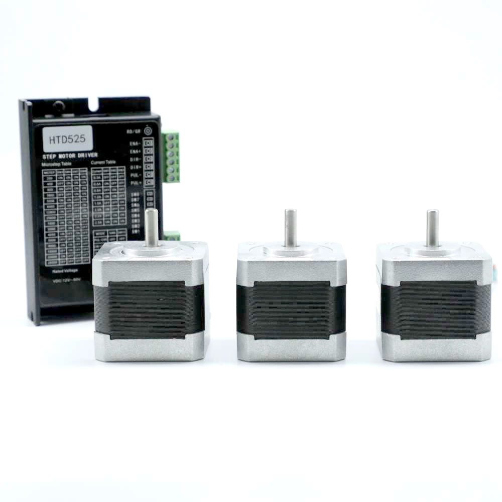
2. Stepper Motor
Select a motor based on your application’s torque, speed, and step angle requirements:
- Step Angle: Most common is 1.8° (200 steps per revolution), but 0.9° (400 steps/rev) offers higher precision.
- Torque Rating: Measured in Nm (e.g., 0.5Nm for small printers, 2Nm for CNC routers). Torque decreases with speed—check the motor’s torque-speed curve.
- Phase Configuration: Bipolar (4 wires) or unipolar (6/8 wires). Bipolar motors offer higher torque and are more common in industrial use.
3. Stepper Motor Driver
The driver acts as an intermediary between the PLC and motor, amplifying low-voltage PLC signals to power the motor. Key features:
- Current Rating: Must match or exceed the motor’s rated current (e.g., 2A driver for a 1.5A motor).
- Microstepping: Allows dividing steps into smaller increments (e.g., 16 microsteps = 0.1125° per microstep) for smoother motion.
- Control Signals: Supports pulse/direction inputs (5V or 24V, compatible with PLC outputs).
Examples: TB6600 (up to 3A, 16 microsteps), Leadshine DM542 (4.2A, industrial-grade).
4. Power Supply
Stepper drivers require two power sources:
- Logic Voltage: 5V or 24V for the driver’s control circuit (often provided by the PLC’s 24V output).
- Motor Voltage: 12–48V DC (higher voltage improves high-speed performance). A 24V, 5A supply works for most 1–2Nm motors.
5. Wiring and Protection
- Shielded Cables: Reduce electrical noise (critical for pulse signals). Use twisted-pair cables for pulse/direction lines.
- Fuses: 10A fuse in the motor power line to protect against short circuits.
- Connectors: Terminal blocks for secure connections (avoid loose wiring, which causes signal loss).
How Stepper Motor-PLC Control Works
Stepper motors operate on a simple principle: each electrical pulse from the PLC tells the motor to move one step. Here’s the detailed workflow:
1. Pulse Signals: The Language of Steppers
- Step Pulses: A train of square-wave pulses from the PLC (e.g., 5V, 100kHz) tells the driver when to move the motor. Each pulse = 1 step (or microstep).
- Direction Signal: A constant voltage (e.g., 24V = clockwise, 0V = counterclockwise) sets the rotation direction.
- Enable Signal (optional): A third signal activates/deactivates the driver (prevents motor overheating when idle).
2. Position Control
To move the motor to a specific position:
- Calculate the total steps needed:
Total Steps = (Target Position / Screw Pitch) × Steps per Revolution × Microstepping
Example: Moving a linear stage 50mm with a 5mm lead screw, 200 steps/rev motor, and 16 microsteps:
50mm / 5mm = 10 rotations → 10 × 200 × 16 = 32,000 steps.
- The PLC sends 32,000 pulses to the driver, which rotates the motor until the target is reached.
3. Speed Control
Speed is determined by pulse frequency (pulses per second, Hz):
Speed (RPM) = (Pulse Frequency × 60) / (Steps per Revolution × Microstepping)
Example: 10,000 Hz with 200 steps/rev and 16 microsteps:
(10,000 × 60) / (200 × 16) = 187.5 RPM.
Higher frequencies increase speed but require sufficient motor voltage to maintain torque.
Step-by-Step: Controlling a Stepper Motor with a PLC
Let’s walk through a practical example: controlling a linear actuator to move a part 100mm at 200 RPM using a Mitsubishi FX5 PLC, TB6600 driver, and 1.8° stepper motor (200 steps/rev).
1. Hardware Setup
Wiring the System
- PLC to Driver Connections:
-
- PLC Y0 (pulse output) → Driver PUL+ (via 2kΩ resistor, if 24V PLC).
-
- PLC Y1 (direction output) → Driver DIR+.
-
- Driver PUL- and DIR- → PLC 0V (common ground).
-
- PLC X0 (start button) → 24V source (normally open).
- Driver to Motor:
-
- Motor A+ → Driver A+.
-
- Motor A- → Driver A-.
-
- Motor B+ → Driver B+.
-
- Motor B- → Driver B-.
- Power Supply:
-
- 24V DC to PLC and driver logic (DIR/PUL).
-
- 24V DC (3A) to driver motor power input (VMOT).
Driver Configuration (TB6600)
- Current Limit: Set to 1.5A (matches motor’s 1.5A rating) using the driver’s potentiometer.
- Microstepping: Set to 16 (DIP switches 1-4: ON-OFF-ON-OFF) for smooth motion.
- Enable: Connect driver EN+ to PLC Y2 (enable signal), EN- to 0V.
2. PLC Programming (Mitsubishi GX Works3)
Define Parameters
- Target Position: 100mm. With a 5mm lead screw, this requires 20 rotations.
- Total Steps: 20 rotations × 200 steps/rev × 16 microsteps = 64,000 steps.
- Speed: 200 RPM → Pulse frequency = (200 × 200 × 16) / 60 = 10,667 Hz.
Write the Logic
- Start Condition: When X0 (start button) is pressed, trigger the pulse output.
- Pulse Instruction: Use the “PLS” (pulse output) command to send 64,000 pulses at 10,667 Hz.
- Direction: Set Y1 to 24V (high) for clockwise movement.
- Enable: Activate Y2 (enable) before sending pulses.
X0 (Start) → [ ] → SET M0M0 → [ ] → PLS Y0 (Pulse: 64000, Frequency: 10667, Y1=1)M0 → [ ] → OUT Y2 (Enable)- Stop Condition: Add an emergency stop (X1) that resets M0 and stops the pulse output.
3. Testing and Calibration
Initial Test
- Dry Run: Disconnect the load and run the program. Verify the motor moves smoothly without hesitation.
- Check Position: Measure the linear movement—if it’s 98mm instead of 100mm, adjust the pulse count (increase by 2% to 65,280 pulses).
Tuning
- Vibration at Low Speeds: Increase microstepping (e.g., 32 microsteps) or add a damping resistor (100Ω) in series with the motor leads.
- Loss of Steps at High Speeds: Increase motor voltage (from 24V to 36V) to improve torque at higher frequencies.
- Overheating: Reduce driver current if the motor gets too hot (above 70°C) or add a heatsink to the driver.
Advanced Control Techniques
For complex applications, enhance your PLC-stepper system with these techniques:
1. Ramp Control (S-Curve Acceleration)
Abrupt speed changes cause vibration and stress. Use PLC programming to create smooth acceleration/deceleration profiles:
- Start at 500 Hz, increase by 100 Hz every 10ms until reaching 10,000 Hz.
- Decelerate similarly before stopping. Most PLCs have built-in “motion profile” instructions (e.g., Siemens “MC_MoveAbsolute” with ramp settings).
2. Multi-Axis Coordination
PLCs with multiple pulse outputs can control multiple steppers simultaneously (e.g., X and Y axes in a CNC machine). Use software like TIA Portal to synchronize movements, ensuring axes reach their targets at the same time.
3. Feedback for Semi-Closed Loop Control
While steppers are open-loop, add a linear encoder to the load (not the motor) for position verification:
- PLC compares encoder feedback to the target position.
- If error exceeds 0.5mm, send a correction pulse. This combines stepper simplicity with servo-like accuracy.
Troubleshooting Common Issues
Even with careful setup, problems may arise. Here’s how to diagnose them:
1. Motor Doesn’t Move
- Check Power: Ensure the driver’s VMOT has 24V and the logic inputs (PUL/DIR) receive 5V/24V from the PLC.
- Verify Signals: Use an oscilloscope to check for pulses at Y0 (should see a 10kHz square wave when active).
- Driver Errors: Most drivers have LED indicators—red LED may mean overcurrent (check wiring for shorts) or overheating (improve ventilation).
2. Loss of Steps
- Insufficient Torque: The motor can’t handle the load at the current speed. Reduce speed, increase voltage, or upgrade to a higher-torque motor.
- Electrical Noise: Shielded cables are loose—reconnect and ground the shield to the PLC’s chassis.
- Driver Overload: Current setting is too low—increase driver current (but not above motor rating).
3. Erratic Movement
- Loose Connections: Wiggle wires at the driver and PLC—intermittent movement indicates a loose pulse or ground connection.
- PLC Program Errors: Check for incorrect pulse counts or frequency settings. Use the PLC’s monitoring tool to verify pulse output.
- Driver Interference: Keep motor power cables away from PLC signal wires to prevent electromagnetic interference (EMI).
Applications of PLC-Stepper Systems
PLC-controlled stepper motors excel in these scenarios:
- 3D Printers: Precise layer deposition (0.1mm accuracy) using 16 microsteps.
- Packaging Machines: Indexing conveyor belts to position boxes for labeling (±0.5mm repeatability).
- Textile Machinery: Controlling thread tension via precise roller positioning.
- Medical Devices: Moving syringe pumps at 0.1mm/s for accurate drug delivery.
Conclusion
Controlling a stepper motor with a PLC is a straightforward process that combines the simplicity of steppers with the flexibility of PLC logic. By understanding pulse-based control, selecting compatible components, and following careful wiring and programming steps, you can build systems that deliver reliable, precise motion for industrial and commercial applications.
What Is an Inverter Generator
How to Control a Servo Motor with a PLC
Related Article

Brushless DC (BLDC) motors are widely used in EVs, drones, industrial machinery, and robotics for their efficiency and long lifespan. Unlike brushed motors—where reversing direction only requires swapping power leads—BLDC motors rely on electronic commutation, making direction reversal more nuanced.
How to Reverse Direction in Brushless Motors
Brushed and brushless DC motors are two of the most common electric motor designs, powering everything from toys to electric vehicles. While both convert electrical energy to mechanical motion, their internal structures, performance, and use cases differ drastically.
What’s the Difference Between a Brushed and Brushless Motor
Brushed DC motors are reliable, but wear and tear over time can lead to failure. Whether you’re troubleshooting a power tool, household appliance, or industrial conveyor motor, knowing the signs of a bad brushed motor saves time and prevents further damage.
How to Know If a Brushed Motor Is Bad
