


How to Control the Speed of a DC Motor
2025-06-24
How to Control the Speed of a DC Motor?
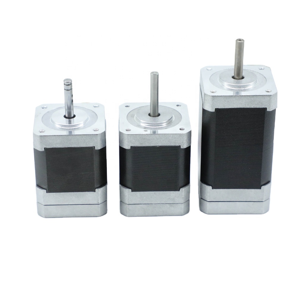
Direct Current (DC) motors are ubiquitous in modern technology, powering everything from small household appliances like blenders and fans to industrial machinery and electric vehicles. One of the key advantages of DC motors is the ability to precisely control their rotational speed, which is crucial for applications requiring variable performance. In this blog, we'll explore the fundamental principles and practical methods for controlling DC motor speed, covering both electronic and mechanical approaches.
1. Understanding DC Motor Speed Principles
Before diving into control methods, it's essential to grasp the basic physics behind DC motor speed. The rotational speed (measured in revolutions per minute, RPM) of a DC motor is primarily determined by two factors:
- Armature Voltage (V): For a given motor, speed is approximately proportional to the applied voltage when the load torque is constant.
- Field Flux (Φ): Speed is inversely proportional to the magnetic flux produced by the field windings in separately excited or shunt-wound motors.
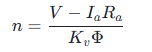
The governing equation for a shunt or separately excited DC motor is:
Where:
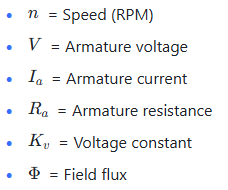
This equation forms the basis for most speed control techniques, which either adjust voltage, flux, or mechanical load characteristics.
2. Electronic Speed Control Methods
2.1 Voltage Regulation (Armature Voltage Control)
The most straightforward way to control speed is by adjusting the armature voltage. This method is ideal for motors operating below their rated speed and works best with separately excited or shunt-wound motors.
2.1.1 Linear Voltage Controllers
- How it works: Uses linear power devices (such as transistors in linear mode) to drop excess voltage, providing a variable DC output to the motor.
- Advantages: Simple circuit design, low electromagnetic interference (EMI), and smooth speed control.
- Disadvantages: Poor energy efficiency (power is dissipated as heat), limited current capacity, and suitability only for low-power applications.
- Applications: Small hobby motors, simple robotic systems, or prototypes.
2.1.2 Switching Power Supplies (DC-DC Converters)
- Buck Converters: Step down the input voltage to a lower DC voltage. By switching the power device (MOSFET or IGBT) on and off at high frequency, they achieve high efficiency (80-95%).
- Boost Converters: Less common for speed control since we usually reduce voltage, but can increase voltage for motors needing temporary speed boosts.
- Advantages: High efficiency, suitable for medium to high-power motors, and compact size.
- Disadvantages: More complex circuitry, potential EMI issues that require filtering.
2.2 Pulse Width Modulation (PWM) Control
PWM is one of the most popular methods for DC motor speed control, especially in low to medium-power applications.
2.2.1 PWM Working Principle
- Duty Cycle: The percentage of time the power supply is connected to the motor during a switching cycle. For example, a 50% duty cycle means the motor is powered half the time and off the other half.
- Effective Voltage: The average voltage applied to the motor is proportional to the duty cycle. A 100% duty cycle gives full voltage (maximum speed), while 0% means no power (stop).
- Formula:

2.2.2 Why PWM is Popular
- High Efficiency: No power is wasted as heat in the controller (when using ideal switches), unlike linear regulators.
- Smooth Control: At high switching frequencies (typically 10-20 kHz), the motor doesn't detect the on/off pulses, resulting in smooth rotation.
- Cost-Effective: Can be implemented with simple microcontroller circuits (e.g., Arduino, Raspberry Pi) using built-in PWM pins.
2.2.3 PWM Circuit Components
- H-Bridge Controller: Allows bidirectional control (forward/reverse) and PWM speed control. Essential for applications needing direction change, like robotic arms.
- MOSFET/Transistor Drivers: Amplify the microcontroller's PWM signal to drive the motor's higher current requirements.
2.3 Field Flux Control (Field Weakening)
This method is used to operate the motor above its rated speed by reducing the magnetic field flux, which is only feasible for motors with adjustable field windings (e.g., shunt or separately excited motors).
- How it works: Decrease the current through the field winding, reducing \(\Phi\). From the speed equation, lower flux increases speed (since \(n \propto 1/\Phi\)).
- Limitations:
-
- Speed increase is limited (typically 2-3 times rated speed) due to mechanical constraints.
-
- Reduced torque capability (torque is proportional to flux and armature current, \(T \propto \Phi I_a\)), so it's only suitable for constant-power loads.
- Applications: Electric vehicles (for high-speed cruising after initial torque-rich acceleration), machine tools needing wide speed ranges.
3. Mechanical Speed Control Methods
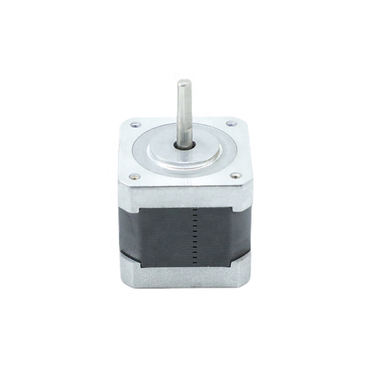
While electronic methods focus on electrical parameters, mechanical approaches modify the motor's output characteristics through gearing or load adjustment.
3.1 Gear Systems and Transmission
- Gear Reduction/Increase:
-
- Reduction Gearboxes: Increase torque while reducing speed (e.g., a 10:1 gearbox reduces output speed by 10x but increases torque by 10x).
-
- Speed Increasers: Less common, as they reduce torque significantly.
- Applications: Robotics (need high torque at low speeds), conveyor belts, industrial machinery.
- Advantage: Provides physical speed-torque conversion without electrical complexity.
- Disadvantage: Adds mechanical complexity, weight, and potential maintenance needs (e.g., gear wear).
3.2 Load Torque Adjustment
- Changing the mechanical load on the motor indirectly affects speed. For example:
-
- Reducing friction in the system allows the motor to spin faster at the same voltage.
-
- Using clutches or brakes to vary the effective load torque.
- Note: This is more of a reactive control method and is rarely used alone for precise speed regulation.
4. Closed-Loop Speed Control with Feedback Systems
For applications requiring precise speed regulation (e.g., CNC machines, drones), open-loop methods (like simple PWM) aren't sufficient due to load variations or voltage fluctuations. Closed-loop systems use feedback to maintain desired speed.
4.1 Feedback Sensors
- Tachometers: Generate a voltage proportional to speed, commonly used in industrial motors.
- Encoder: Provides digital pulses per revolution, allowing precise speed calculation (e.g., 1000 pulses per revolution for high resolution).
- Hall Effect Sensors: Detect rotor position in brushless DC motors, which can also be used for speed estimation.
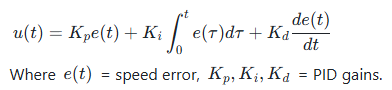
4.2 PID Controllers
- Proportional-Integral-Derivative (PID) Control:
-
- Compares the actual speed (from sensor) with the desired speed (setpoint).
-
- Adjusts the control input (e.g., PWM duty cycle or armature voltage) to minimize the error.
- Formula:
- Advantages: Robust against disturbances, maintains speed stability under varying loads.
- Challenges: Requires sensor installation and careful tuning of PID parameters.
5. Choosing the Right Method for Your Application
The optimal speed control method depends on:
- Power Requirements: Low-power (PWM with microcontroller), medium-power (DC-DC converters), high-power (industrial drives with field weakening).
- Precision Needs: Open-loop (simple PWM) vs. closed-loop (PID with encoders) for high accuracy.
- Torque-Speed Characteristics: Gear systems for torque-intensive tasks, field weakening for high-speed operation.
- Cost and Complexity: Linear controllers are cheap but inefficient; PID systems are precise but expensive.
Conclusion
Controlling a DC motor's speed involves a mix of electrical engineering principles, mechanical design, and feedback control theory. Whether you're building a simple robot, a CNC machine, or an electric vehicle, understanding the strengths and limitations of each method is key. PWM offers a balance of simplicity and efficiency for most hobby and mid-power applications, while closed-loop systems with PID control excel in precision-critical scenarios. By combining electronic and mechanical approaches, you can create robust speed control solutions that meet the specific demands of your project.
Remember to always consider safety (e.g., overcurrent protection) and compatibility between components (motor voltage/current ratings, controller capabilities). With the right approach, you'll achieve smooth, reliable speed control for your DC motor application.
What Is a Stepper Motor
How to Construct a DC Motor
Related Article

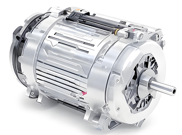
Brushless DC (BLDC) motors are widely used in EVs, drones, industrial machinery, and robotics for their efficiency and long lifespan. Unlike brushed motors—where reversing direction only requires swapping power leads—BLDC motors rely on electronic commutation, making direction reversal more nuanced.
How to Reverse Direction in Brushless Motors
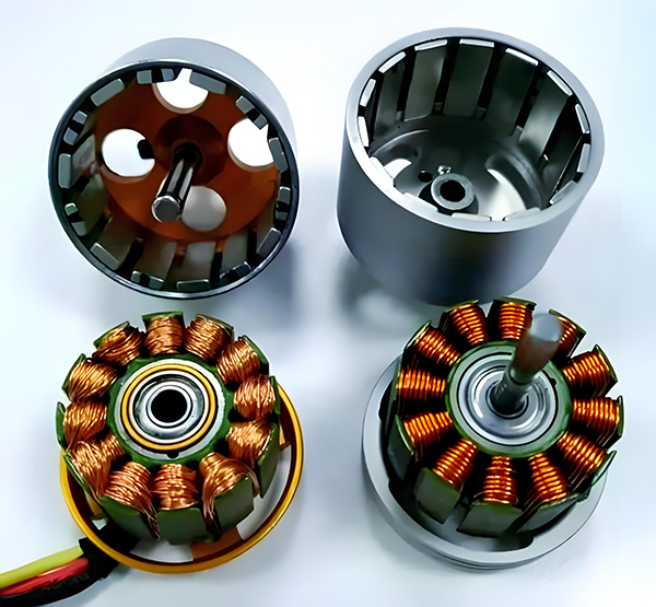
Brushed and brushless DC motors are two of the most common electric motor designs, powering everything from toys to electric vehicles. While both convert electrical energy to mechanical motion, their internal structures, performance, and use cases differ drastically.
What’s the Difference Between a Brushed and Brushless Motor
Brushed DC motors are reliable, but wear and tear over time can lead to failure. Whether you’re troubleshooting a power tool, household appliance, or industrial conveyor motor, knowing the signs of a bad brushed motor saves time and prevents further damage.
How to Know If a Brushed Motor Is Bad
