


How to Make a Photoelectric Sensor
2025-07-09
How to Make a Photoelectric Sensor?
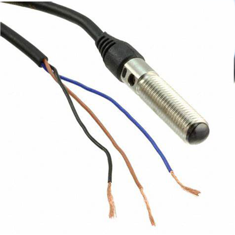
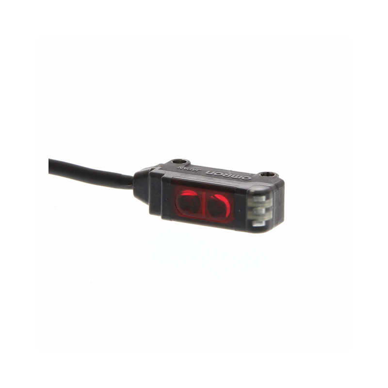
A photoelectric sensor is a practical device that detects objects by using light. It operates based on the principle of light emission and reception—when light from a source is interrupted or reflected by an object, the sensor responds accordingly. Building your own photoelectric sensor is a great way to understand its working mechanism. Here’s a step-by-step guide to help you create one.
Prepare the Materials
Before starting, gather all the necessary components. Having everything ready will make the assembly process smoother.
Essential Components
- LED (Light-Emitting Diode): Serves as the light source. A visible light LED (like red or green) is recommended for easy observation.
- Photodiode: Detects the light emitted by the LED. Choose one that matches the wavelength of the LED for better sensitivity.
- Resistors: Two resistors (values around 220Ω and 10kΩ work for most setups) to control current flow and protect components.
- Breadboard: A solderless platform to assemble the circuit, allowing easy adjustments.
- Jumper Wires: To connect the components on the breadboard.
- Power Supply: A 3-6V battery or a USB power adapter (with appropriate voltage regulation) to power the circuit.
- Multimeter: Useful for testing voltage and current during the process.
Assemble the Circuit
Once you have all the materials, it’s time to build the circuit. Follow these steps carefully to ensure proper connections.
Set Up the Breadboard
First, place the breadboard on a flat surface. The breadboard has rows and columns of holes; the holes in the same row are electrically connected, which helps in forming the circuit.
Connect the LED
- Insert the LED into the breadboard. Note that LEDs have polarity: the longer leg is the anode (positive), and the shorter one is the cathode (negative).
- Connect one end of a 220Ω resistor to the anode of the LED.
- Connect the other end of this resistor to the positive terminal of the power supply on the breadboard.
- Connect the cathode of the LED to the negative terminal (ground) of the power supply using a jumper wire.
Connect the Photodiode
- Insert the photodiode into the breadboard. Similar to the LED, photodiodes have polarity—check the datasheet to identify the anode and cathode.
- Attach one end of a 10kΩ resistor to the anode of the photodiode.
- Connect the other end of this resistor to the positive terminal of the power supply.
- Connect the cathode of the photodiode to the ground.
Complete the Power Connection
- Connect the positive wire of the power supply to the positive rail on the breadboard.
- Connect the negative wire of the power supply to the negative rail (ground) on the breadboard. Ensure all ground connections are linked.
Test and Adjust the Sensor
After assembling the circuit, it’s crucial to test if the sensor works correctly and make adjustments if needed.
Initial Test
- Turn on the power supply. The LED should light up, emitting light.
- Take an object (like a piece of cardboard) and move it between the LED and the photodiode. Observe the photodiode’s behavior using a multimeter connected across it. When the object blocks the light, the voltage across the photodiode should change.
Troubleshooting
- If the LED doesn’t light up, check the resistor value and the connections. Ensure the LED is inserted with the correct polarity.
- If there’s no voltage change when blocking the light, verify the photodiode’s connections and polarity. Try using a different photodiode that matches the LED’s wavelength.
Fine-Tuning
- Adjust the distance between the LED and the photodiode. A shorter distance may make the sensor more sensitive, while a longer distance can increase the detection range.
- Replace the resistors with different values if the sensor is too sensitive or not sensitive enough. Experiment to find the optimal setup for your needs.
By following these steps, you can successfully build a simple photoelectric sensor. This project not only helps you understand the basic principles of photoelectric detection but also allows you to customize the sensor for various applications, such as object counting or proximity sensing.
What Is a Proximity Sensor
What Are Photoelectric Sensors Used For
Related Article

Brushless DC (BLDC) motors are widely used in EVs, drones, industrial machinery, and robotics for their efficiency and long lifespan. Unlike brushed motors—where reversing direction only requires swapping power leads—BLDC motors rely on electronic commutation, making direction reversal more nuanced.
How to Reverse Direction in Brushless Motors
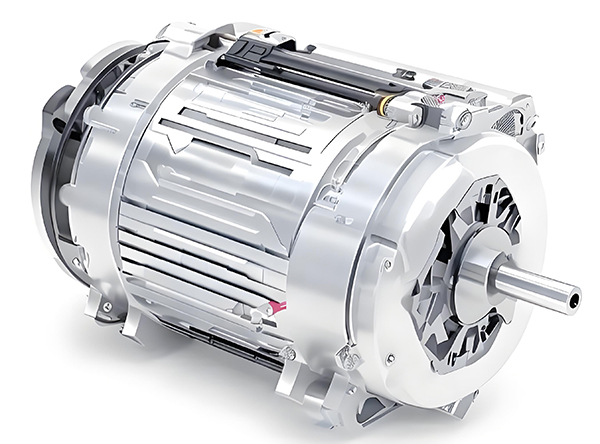
Brushed and brushless DC motors are two of the most common electric motor designs, powering everything from toys to electric vehicles. While both convert electrical energy to mechanical motion, their internal structures, performance, and use cases differ drastically.
What’s the Difference Between a Brushed and Brushless Motor
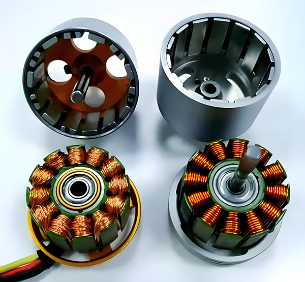
Brushed DC motors are reliable, but wear and tear over time can lead to failure. Whether you’re troubleshooting a power tool, household appliance, or industrial conveyor motor, knowing the signs of a bad brushed motor saves time and prevents further damage.
How to Know If a Brushed Motor Is Bad
