


How to Test a Photoelectric Sensor
2025-07-06
How to Test a Photoelectric Sensor?
Photoelectric sensors play a critical role in countless industrial, commercial, and even consumer applications. These devices detect the presence or absence of objects by using light as a medium, making them essential in automation systems, quality control, packaging lines, and more. However, like any precision instrument, their performance can degrade over time due to environmental factors, mechanical stress, or simple wear and tear. Regular testing is crucial to ensure they function accurately and reliably. In this guide, we'll walk through the step-by-step process of testing a photoelectric sensor, covering everything from preparation to troubleshooting common issues.
Understanding Photoelectric Sensor Basics Before Testing
What Is a Photoelectric Sensor?
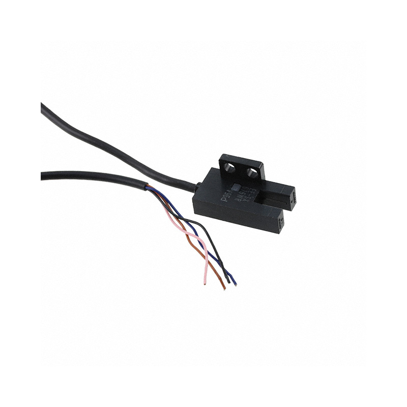
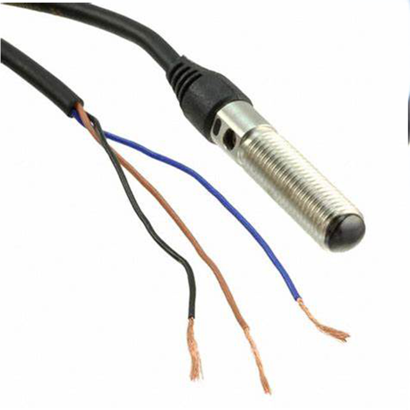
A photoelectric sensor consists of two main components: a transmitter that emits a light beam (usually infrared, visible red, or laser) and a receiver that detects the light. Depending on the type, they operate in different modes:
- Through-Beam (Direct-Beam) Sensors: The transmitter and receiver are separate units, with the beam passing directly between them. An object blocks the beam to trigger a signal.
- Diffuse-Reflective Sensors: Both transmitter and receiver are in the same housing. The sensor detects light reflected back from the object.
- Retroreflective Sensors: The transmitter and receiver are co-located, using a retroreflector (a special mirror) to bounce the light back to the receiver. An object interrupts the reflected beam.
Key Specifications to Know
Before testing, familiarize yourself with the sensor's datasheet to understand:
- Detection Range: The maximum distance at which the sensor can reliably detect an object.
- Response Time: How quickly the sensor reacts to a change in light intensity.
- Light Source Type: Infrared sensors are common for general use, while laser sensors offer higher precision.
- Output Type: Digital (switching) or analog (voltage/current output), which determines how you'll measure the signal.
- Environmental Ratings: IP ratings for dust/water resistance and temperature limits that affect testing conditions.
Preparing for the Test
Gather Necessary Tools
You'll need these essential items:
- Multimeter: To measure voltage or current outputs (for analog sensors) or check digital output states.
- Oscilloscope: For analyzing signal integrity and response time, especially for high-speed applications.
- Signal Generator (Optional): To simulate input signals if testing integrated systems.
- Test Objects: Objects of various materials, sizes, and colors (since reflectivity varies—e.g., black vs. white surfaces for diffuse sensors).
- Calibration Tools: A precision ruler or gauge for distance measurements, and a retroreflector if testing retroreflective sensors.
- Power Supply: Matching the sensor's voltage requirements (e.g., 12-24V DC or 110-240V AC, depending on the model).
Set Up a Controlled Environment
- Lighting: Minimize ambient light interference, especially for sensors operating in visible wavelengths. Use blackout curtains or test in a dimly lit area.
- Mounting: Secure the sensor and any separate components (like transmitters, receivers, or retroreflectors) on a stable platform to prevent misalignment during testing.
- Wiring: Connect the sensor to the power supply and measurement tools according to the manufacturer's wiring diagram. Double-check polarity for DC-powered sensors to avoid damage.
Step-by-Step Testing Procedures
1. Functional Test for Basic Operation
For Through-Beam Sensors
- Step 1: Position the transmitter and receiver directly opposite each other, within the specified detection range. Align them carefully so the beam hits the center of the receiver.
- Step 2: Apply power to the sensor. The receiver should indicate a "light-on" state (usually via an LED) when the beam is unobstructed.
- Step 3: Introduce a test object between the transmitter and receiver. The receiver's output should switch to "light-off," indicating the beam is blocked. Use a non-transparent object large enough to completely interrupt the beam (check the sensor's minimum detectable object size in the datasheet).
For Diffuse-Reflective Sensors
- Step 1: Place a test object within the sensor's specified detection range. Start at a short distance (e.g., 10% of the maximum range) and gradually increase it.
- Step 2: Ensure the object's surface is perpendicular to the sensor's axis for maximum reflectivity. For colored objects, note that dark colors reduce reflectivity—test with the worst-case material if known (e.g., black plastic).
- Step 3: Observe the output signal. The sensor should activate when the object is within range and deactivate when moved beyond the detection limit.
For Retroreflective Sensors
- Step 1: Mount the retroreflector directly across from the sensor, ensuring the beam reflects back to the receiver. Use the alignment marks on the retroreflector for precision.
- Step 2: Check the receiver's "light-on" state when the beam is reflected. Introduce an object between the sensor and retroreflector; the output should switch to "light-off" as the object blocks the reflected beam.
- Step 3: Verify that the retroreflector's alignment isn't compromised—even a slight tilt can reduce signal strength.
2. Range and Sensitivity Test
Measuring Maximum Detection Range
- For Through-Beam: Gradually increase the distance between transmitter and receiver until the sensor fails to detect the object consistently. Record this distance and compare it to the datasheet specification.
- For Diffuse/Retroreflective: Place the test object at increasing distances (incrementally, e.g., 10mm steps) and note the farthest point where the sensor still triggers reliably. Test with both high-reflectivity (white) and low-reflectivity (black) objects to measure the range difference.
Adjusting Sensitivity (If Adjustable)
- Many sensors have sensitivity knobs or digital settings. Turn the sensitivity down to the lowest setting and slowly increase it until the sensor detects the object at the desired range. Ensure it doesn't trigger false positives from background objects or ambient light.
3. Response Time and Signal Integrity Test
- Using an Oscilloscope: Connect the sensor's output to the oscilloscope and trigger a fast-moving object to pass through the detection zone. Measure the time between the object entering the zone and the output signal changing (rise time) and when it exits (fall time). This should match the datasheet's response time specifications.
- Check for Signal Noise: Observe the oscilloscope trace for any spikes or fluctuations when the sensor is stable. Excessive noise may indicate interference from electromagnetic sources (e.g., motors, inverters) or poor grounding. Use shielded cables and ensure proper grounding to mitigate this.
4. Analog Output Calibration (For Analog Sensors)
- Step 1: With no object detected (or fully detected, depending on the sensor's default state), measure the output voltage/current with a multimeter. It should match the "no-object" or "object-present" baseline value (e.g., 0V or 4mA for the lower range, 5V or 20mA for the upper range).
- Step 2: Move the object to the midpoint of the detection range and check the output— it should be approximately halfway between the minimum and maximum values. If not, adjust the sensor's calibration trim pot (if available) or use a digital interface for software calibration.
- Step 3: Verify linearity by taking measurements at multiple points across the range. Plot the results to ensure the output changes proportionally with distance.
Troubleshooting Common Issues
1. No Output Signal
- Possible Causes:
-
- Incorrect wiring (check power supply voltage, polarity, and ground connections).
-
- Misalignment (especially for through-beam and retroreflective sensors—use alignment tools or laser pointers to realign).
-
- Faulty sensor or damaged components (test with a known-good sensor to confirm).
-
- Ambient light overload (use a sensor with a filter for the specific wavelength or increase the signal-to-noise ratio).
2. False Triggers or Inconsistent Detection
- Possible Causes:
-
- Insufficient sensitivity (adjust the sensitivity setting or clean the lens if dirty).
-
- Background objects reflecting light (for diffuse sensors, ensure the detection range is shorter than the distance to background surfaces).
-
- Vibration causing misalignment (加固 mounting brackets and use anti-vibration pads).
-
- Temperature extremes exceeding the sensor's rating (verify operating temperature and install heat shields or heaters if needed).
3. Reduced Detection Range
- Possible Causes:
-
- Dirty lens or retroreflector (clean with a soft, dry cloth—avoid solvents that may damage coatings).
-
- Degraded light emitter (LEDs/lasers have a finite lifespan; replace the sensor if aged).
-
- Incorrect object type (ensure the test object matches the sensor's specified material/color requirements).
Best Practices for Ongoing Maintenance
1. Regular Calibration
- Schedule quarterly or annual calibration using reference objects and tools to ensure long-term accuracy. Document calibration results for traceability.
2. Environmental Monitoring
- Keep the sensor's lens and surrounding area clean from dust, moisture, or debris that can block the light path. Use protective covers in harsh environments.
3. Data Logging
- For critical applications, log sensor outputs over time to detect gradual performance degradation (e.g., declining signal strength in analog sensors).
4. Spare Parts Inventory
- Keep a spare sensor of the same model on hand for quick replacement during failures, along with calibration records to minimize downtime.
Conclusion
Testing a photoelectric sensor requires a systematic approach that accounts for its type, specifications, and operating environment. By following these steps—from understanding basic principles to troubleshooting common issues—you can ensure your sensors operate at peak performance, reducing downtime and improving the reliability of your systems. Remember to always consult the manufacturer's documentation for model-specific instructions, as some sensors may have unique features or testing requirements. Regular maintenance and proactive testing are the keys to maximizing the lifespan and effectiveness of these essential devices.
Whether you're working in a manufacturing plant, a research lab, or a DIY project, mastering sensor testing techniques will help you diagnose problems quickly and maintain optimal system performance. Stay vigilant about environmental factors and follow best practices for calibration and maintenance, and your photoelectric sensors will serve you reliably for years to come.
What Are Photoelectric Sensors Used For
What Is a Photoelectric Sensor
Related Article

Brushless DC (BLDC) motors are widely used in EVs, drones, industrial machinery, and robotics for their efficiency and long lifespan. Unlike brushed motors—where reversing direction only requires swapping power leads—BLDC motors rely on electronic commutation, making direction reversal more nuanced.
How to Reverse Direction in Brushless Motors
Brushed and brushless DC motors are two of the most common electric motor designs, powering everything from toys to electric vehicles. While both convert electrical energy to mechanical motion, their internal structures, performance, and use cases differ drastically.
What’s the Difference Between a Brushed and Brushless Motor
Brushed DC motors are reliable, but wear and tear over time can lead to failure. Whether you’re troubleshooting a power tool, household appliance, or industrial conveyor motor, knowing the signs of a bad brushed motor saves time and prevents further damage.
How to Know If a Brushed Motor Is Bad
