


What Is a Signal Isolator
2025-07-24
What Is a Signal Isolator?
In the complex web of modern electrical and electronic systems, ensuring reliable and accurate signal transmission is paramount. From industrial automation to medical devices, countless applications depend on precise data exchange between components. Yet, electrical noise, ground loops, and voltage differences often threaten this integrity. This is where signal isolators come into play. But what exactly is a signal isolator? This comprehensive guide will unpack its definition, functions, working principles, types, applications, and technical nuances to provide a complete understanding.
Defining Signal Isolators: The Fundamentals
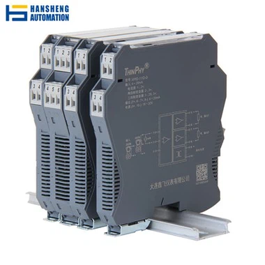
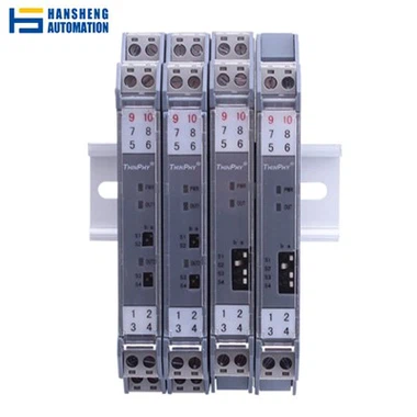
A signal isolator is an electronic device designed to separate electrical signals between two or more circuits while maintaining signal integrity. It creates a barrier that prevents direct electrical conduction between input and output pathways, effectively isolating them from each other. This isolation serves multiple critical purposes: protecting sensitive equipment from voltage spikes, eliminating ground loop interference, and ensuring safe operation in high-voltage environments.
At its core, a signal isolator acts as a "translator" that receives an input signal, processes it through an isolation barrier, and reproduces a corresponding output signal on the other side—all without any direct electrical connection between the two sides. This separation is achieved using various technologies, including optical, magnetic, or capacitive methods, each with unique advantages for specific applications.
Signal isolators are commonly used with analog signals (such as 4-20mA current loops or 0-10V voltage signals) and digital signals (including RS-485, CAN bus, or Ethernet), making them versatile components in diverse electrical systems.
Core Functions of a Signal Isolator
Breaking Electrical Paths to Eliminate Ground Loops
One of the primary functions of a signal isolator is to eliminate ground loops—a common issue in interconnected electrical systems. Ground loops occur when multiple devices in a system are connected to different ground points with slight voltage differences (often just a few millivolts, but potentially higher). These differences create unintended current flows through the signal lines, introducing noise and distortion into measurements or control signals.
A signal isolator breaks this loop by separating the input and output grounds, preventing the flow of stray currents. For example, in a factory automation setup with sensors, controllers, and actuators connected across large distances, ground potential differences of 5V to 10V are not uncommon. A signal isolator placed in the signal path can reduce noise caused by such loops by 40dB to 80dB, ensuring signal accuracy.
Protecting Equipment from Voltage Transients
Electrical systems are vulnerable to voltage spikes and surges, which can originate from lightning strikes, motor switching, or power grid fluctuations. These transients can reach thousands of volts and damage sensitive electronics like microcontrollers, sensors, or data acquisition systems.
Signal isolators provide robust protection by withstanding high isolation voltages—typically ranging from 2.5kV to 10kV (RMS) for industrial models, with specialized versions exceeding 20kV. This isolation acts as a barrier, diverting harmful energy away from sensitive components. For instance, in renewable energy systems, where inverters and monitoring equipment are exposed to high-voltage transients, isolators with 5kV isolation ratings are standard to safeguard control circuits.
Maintaining Signal Integrity During Transmission
While isolating circuits, signal isolators must preserve the original signal’s characteristics—amplitude, frequency, and timing—with minimal distortion. This is critical in applications like process control, where even small signal errors can lead to incorrect measurements or operational failures.
Modern isolators achieve high transmission accuracy, typically within 0.1% to 0.5% of full scale (FS) for analog signals. For example, a 4-20mA current loop isolator will ensure that a 12mA input (representing 50% of a process variable) is reproduced as 12mA ±0.06mA at the output. This level of precision is essential in pharmaceutical manufacturing, where strict temperature and pressure controls depend on accurate signal transmission.
Enabling Safe Operation in Hazardous Environments
In environments where electrical safety is critical—such as medical devices, explosive atmospheres, or high-voltage systems—signal isolators prevent dangerous current leakage between circuits. In medical equipment like ECG monitors, isolators with reinforced isolation (meeting IEC 60601-1 standards) ensure that patient-connected circuits are galvanically separated from mains-powered components, limiting leakage current to less than 10µA to prevent electric shock.
Similarly, in oil and gas facilities, isolators certified for hazardous areas (ATEX or IECEx) prevent sparks from non-intrinsically safe circuits from igniting flammable gases, serving as a vital safety barrier.
How Signal Isolators Work: A Technical Breakdown
The Three-Stage Operation Process
Signal isolators typically operate in three key stages, each contributing to their ability to isolate while transmitting signals:
- Input Stage: The incoming signal (analog or digital) is first conditioned to match the isolator’s internal requirements. For analog signals, this may involve amplification, filtering, or conversion to a standardized format (e.g., 0-5V to 4-20mA). Digital signals may undergo buffering or level shifting to ensure compatibility with the isolation mechanism.
- Isolation Stage: This is the core of the isolator, where electrical separation is achieved using one of three primary technologies:
-
- Optical Isolation: Uses a light-emitting diode (LED) and a photodetector (phototransistor or photodiode) enclosed in an opaque package. The input signal modulates the LED’s light output, which is then detected and converted back to an electrical signal on the output side—with no direct electrical connection.
-
- Magnetic Isolation: Employs a transformer or inductor to transfer signals via magnetic fields. The input signal is used to generate a varying magnetic field in a primary coil, which induces a corresponding current in a secondary coil (electrically isolated from the primary). This method is ideal for high-frequency signals up to several megahertz.
-
- Capacitive Isolation: Relies on capacitive coupling between two electrodes. The input signal creates an electric field across a dielectric barrier, inducing a matching signal in the output electrode. Capacitive isolators offer high bandwidth and are often used in digital communication interfaces like USB or Ethernet.
- Output Stage: The isolated signal is conditioned again to meet the requirements of the receiving circuit—adjusting voltage levels, current ranges, or signal type (e.g., converting a photodetector’s current to a voltage signal). This stage may also include filtering to remove noise introduced during isolation.
Key Performance Metrics in Operation
Several parameters define an isolator’s effectiveness:
- Isolation Voltage: The maximum voltage that can be safely applied between input and output circuits without breakdown. This is specified as peak (e.g., 10kV peak) or RMS (e.g., 5kV RMS) and is tested over a defined duration (1 minute or 1 second).
- Common-Mode Rejection Ratio (CMRR): Measures the isolator’s ability to reject noise that appears simultaneously on both input and output grounds. High CMRR (typically 80dB to 120dB at 50/60Hz) ensures that line noise or ground voltage differences do not corrupt the signal.
- Bandwidth: The range of signal frequencies the isolator can transmit without significant attenuation. Analog isolators for sensor signals often have bandwidths of 1kHz to 10kHz, while digital isolators for data communication may support frequencies up to 100MHz or higher.
- Response Time: The time taken for the output signal to reflect a change in the input. For industrial control, response times under 10µs are typical to ensure timely system reactions.
Types of Signal Isolators: Classifications and Applications
By Isolation Technology
Optical Isolators
Optical (or optocoupler) isolators are the most common type, leveraging light for signal transfer. They offer excellent isolation (up to 10kV) and are immune to electromagnetic interference (EMI). Their limitations include lower bandwidth (typically up to 1MHz) and temperature-dependent performance. They are widely used in consumer electronics, automotive systems, and low-speed industrial controls. For example, in automotive ECUs, optical isolators separate sensor inputs from microcontroller circuits to protect against voltage spikes from the vehicle’s electrical system.
Magnetic Isolators
Magnetic isolators use transformers or planar inductors to transfer signals via magnetic flux. They support higher bandwidths (up to 1GHz) and better linearity than optical types, making them suitable for high-speed digital signals (e.g., CAN FD, Ethernet) and wideband analog signals. In industrial Ethernet switches, magnetic isolators with 2.5kV isolation enable communication between fieldbus devices and control systems while withstanding industrial EMI.
Capacitive Isolators
Capacitive isolators use electric fields to couple signals across a dielectric barrier. They combine high bandwidth (up to 100MHz) with low power consumption and are ideal for compact designs. However, they are sensitive to common-mode transient immunity (CMTI)—a measure of resistance to fast voltage spikes. Capacitive isolators with CMTI ratings above 50kV/µs are used in power electronics, such as motor drives, to isolate gate drivers from high-voltage switching circuits.
By Signal Type
Analog Signal Isolators
Designed for continuous signals like voltage (0-10V), current (4-20mA), or thermocouple outputs, these isolators preserve signal linearity and accuracy. They are critical in process industries—for example, isolating temperature sensor signals (PT100 or thermocouple) from PLC inputs in chemical plants, where ground loops can corrupt temperature readings by several degrees Celsius.
Digital Signal Isolators
Handle discrete signals (on/off) or serial data (SPI, I2C, UART). They ensure reliable communication between digital circuits in noisy environments. In smart grid applications, digital isolators protect communication modules (using RS-485) from voltage surges on power lines, ensuring uninterrupted data transmission between meters and control centers.
Practical Applications Across Industries
Industrial Automation and Process Control
In manufacturing plants, signal isolators are ubiquitous in control loops connecting sensors, transmitters, and PLCs. They eliminate ground loops caused by long cable runs and varying ground potentials between equipment. For example, in a water treatment facility, 4-20mA isolators separate pH sensor signals from SCADA systems, ensuring accurate chemical dosing by preventing noise from pumps and motors from distorting measurements. Isolators with 3kV isolation and 0.1% accuracy are standard in such applications.
Medical Devices
Medical equipment demands the highest safety standards, and signal isolators play a key role in patient protection. In MRI machines, isolators with reinforced isolation (meeting IEC 60601-1) separate the high-voltage gradient coils from patient monitoring systems, preventing electrical hazards. Similarly, in infusion pumps, isolators ensure that battery-powered control circuits are isolated from AC mains, limiting leakage current to safe levels (≤5µA).
Energy and Power Systems
In power generation and distribution, signal isolators connect high-voltage equipment (transformers, circuit breakers) to low-voltage control systems. They withstand transient voltages from switching operations and protect SCADA systems from noise. In solar inverter systems, isolators with 6kV isolation ratings separate DC string current sensors from inverter control boards, ensuring accurate power monitoring despite high-voltage DC bus fluctuations.
Transportation
Automotive, aerospace, and railway systems rely on signal isolators to manage harsh electrical environments. In electric vehicles (EVs), isolators with 4kV isolation protect battery management systems (BMS) from high-voltage traction circuits, while ensuring accurate current and voltage measurements for state-of-charge calculations. In aircraft, isolators certified to DO-160 standards isolate avionics sensors from power distribution systems, withstanding vibration and extreme temperature ranges (-55°C to +125°C).
Telecommunications
In telecom infrastructure, signal isolators protect sensitive communication equipment from power line noise and lightning-induced surges. They isolate DSL modems from telephone lines, preventing voltage spikes from damaging internal circuitry. High-speed digital isolators (supporting 1Gbps) are also used in fiber optic transceivers to separate data lines from power supplies, ensuring reliable signal transmission over long distances.
Key Technical Specifications to Consider
Isolation Rating
The maximum voltage the isolator can withstand between input and output, specified as:
- Working Voltage (VIOWM): Continuous safe operating voltage (e.g., 250V RMS).
- Isolation Voltage (VISO): Peak voltage for short-duration testing (e.g., 5kV for 1 minute).
- Reinforced Isolation: Highest safety level, required for medical and high-risk applications (e.g., 4kV VISO per IEC 61010).
Transmission Accuracy
For analog isolators, this is the maximum deviation from ideal signal reproduction, typically 0.1% to 0.5% FS. Higher accuracy (0.05% FS) is needed in calibration equipment or precision measurement systems.
Bandwidth
The frequency range over which the isolator operates without significant signal loss. Analog isolators for sensors may require 1kHz bandwidth, while high-speed digital isolators need 100MHz or more.
Common-Mode Transient Immunity (CMTI)
Critical for digital isolators, CMTI measures resistance to fast voltage spikes across the isolation barrier. Values above 25kV/µs are necessary for motor drives and power converters, where switching transients are common.
Environmental Ratings
Operating temperature range (-40°C to +85°C for industrial, -55°C to +125°C for automotive), humidity tolerance, and vibration resistance (per IEC 60068 standards) ensure reliability in harsh conditions.
Conclusion
A signal isolator is far more than a simple circuit component—it is a critical safeguard for electrical systems, ensuring reliable signal transmission while protecting equipment, personnel, and processes from electrical hazards. By breaking ground loops, blocking noise, and maintaining signal integrity, isolators enable the safe and efficient operation of systems ranging from industrial robots to life-saving medical devices.
What Is a Solenoid Valve
What Do Power Inverters Do
Related Article

Brushless DC (BLDC) motors are widely used in EVs, drones, industrial machinery, and robotics for their efficiency and long lifespan. Unlike brushed motors—where reversing direction only requires swapping power leads—BLDC motors rely on electronic commutation, making direction reversal more nuanced.
How to Reverse Direction in Brushless Motors
Brushed and brushless DC motors are two of the most common electric motor designs, powering everything from toys to electric vehicles. While both convert electrical energy to mechanical motion, their internal structures, performance, and use cases differ drastically.
What’s the Difference Between a Brushed and Brushless Motor
Brushed DC motors are reliable, but wear and tear over time can lead to failure. Whether you’re troubleshooting a power tool, household appliance, or industrial conveyor motor, knowing the signs of a bad brushed motor saves time and prevents further damage.
How to Know If a Brushed Motor Is Bad
