


How to Construct a DC Motor
2025-06-20
How to Construct a DC Motor
Constructing a DC motor can be an exciting and educational project, whether you're a student looking to delve deeper into the principles of electromagnetism, an electronics enthusiast, or an engineer exploring motor design. Understanding the process of building a DC motor not only gives you hands - on experience but also provides valuable insights into how these essential devices work. In this comprehensive blog post, we'll walk you through the detailed steps of constructing a DC motor, from gathering the necessary materials to the final testing and debugging.
Preparation: Gathering Materials and Tools
Essential Materials
- Magnetic Material for the Stator: For the stator, which generates the magnetic field, you can use permanent magnets. Neodymium - iron - boron (NdFeB) magnets are a popular choice due to their strong magnetic properties. These magnets can be purchased in various shapes, such as disc - shaped or bar - shaped, depending on your design requirements. Another option is to use soft iron cores with wound coils to create an electromagnet for the stator.
- Armature Materials: The armature is the rotating part of the motor. You'll need a cylindrical core made of laminated soft iron to reduce eddy current losses. The core can be crafted from multiple thin sheets of iron stacked together. Additionally, you'll require insulated copper wire of an appropriate gauge. The gauge of the wire depends on the power and current requirements of your motor. Thicker wires can carry more current but may be more difficult to wind.
- Commutator Materials: For a brushed DC motor, the commutator is crucial. You can make a commutator using copper strips. These strips need to be insulated from each other. A common method is to use a cylindrical form, such as a plastic tube, and attach the copper strips around it, separated by thin insulating materials like mica or plastic sheets.
- Brushes: Brushes are used to transfer electrical current to the commutator. Carbon brushes are commonly used due to their good electrical conductivity and wear - resistant properties. You can find pre - made carbon brushes in electronics stores, or you can make your own by shaping carbon blocks and attaching wires for electrical connection.
- Shaft and Bearings: A shaft is needed to support the armature and allow it to rotate. It can be made of metal, such as steel or aluminum. Bearings, either ball bearings or bushings, are used to reduce friction between the shaft and the motor housing. Ball bearings generally offer lower friction and longer lifespan but are more expensive, while bushings are simpler and more cost - effective.
- Motor Housing: The motor housing provides structural support and protection for the internal components. It can be made of materials like plastic, aluminum, or steel. The housing should be designed to accommodate the stator, armature, commutator, and other components while allowing for proper ventilation to dissipate heat.
Required Tools
- Wiring and Soldering Tools: A soldering iron, solder, and soldering flux are essential for making electrical connections. You'll use these tools to attach the wires to the commutator, armature windings, and other components. Additionally, wire cutters and strippers will help you prepare the wires for soldering.
- Mechanical Tools: A set of screwdrivers, wrenches, and pliers will be useful for assembling and disassembling the motor components. You may also need a drill and drill bits if you need to make holes in the motor housing or other parts for mounting purposes.
- Measuring Tools: A multimeter is crucial for testing the electrical properties of the motor during construction. It can be used to measure resistance, voltage, and continuity. A ruler or caliper will help you measure the dimensions of components accurately during the construction process.
Building the Stator
Permanent Magnet Stator
If you choose to use permanent magnets for the stator, start by determining the arrangement of the magnets. For a simple design, you can place the magnets around the inner circumference of the motor housing in an alternating north - south pole pattern. Use a strong adhesive, such as epoxy resin, to firmly attach the magnets to the housing. Make sure the magnets are evenly spaced and securely fastened to ensure a consistent magnetic field.
Electromagnet Stator
For an electromagnet stator, first, shape the soft iron core into the desired form, usually a cylindrical or rectangular shape. Then, carefully wind the insulated copper wire around the core. The number of turns of the wire depends on the desired magnetic field strength and the power supply you plan to use. Use a winding tool or wrap the wire by hand, ensuring that the layers are tightly and evenly wound. After winding, connect the two ends of the wire to terminals or leads that will be used to supply electrical current to the coil.
Fabricating the Armature
Preparing the Armature Core
Take the laminated soft iron core and ensure it is clean and free of any debris. If necessary, sand the surface lightly to remove any roughness that could interfere with the winding process. The core should be cylindrical and have a smooth surface to allow for even winding of the copper wire.
Winding the Armature
Begin winding the insulated copper wire around the armature core. Start from one end of the core and make a small loop to secure the starting end of the wire. Then, wind the wire tightly around the core in a helical pattern, making sure each turn is adjacent to the previous one without overlapping too much. As you wind, keep the tension on the wire consistent to ensure a uniform winding. The number of layers of winding can vary depending on your design. After completing the winding, leave enough length of wire at the end for connection to the commutator.
Creating the Commutator (for Brushed DC Motors)
Shaping the Commutator Base
Take the plastic tube or other cylindrical form that will serve as the base for the commutator. Cut it to the appropriate length based on the size of your motor and the number of commutator segments you plan to have. Make sure the surface of the tube is smooth.
Attaching the Copper Strips
Cut the copper strips to the appropriate length and width. The width of the strips should be sufficient to make good electrical contact with the brushes. Attach the copper strips around the plastic tube, leaving a small gap between each strip for insulation. Use the insulating material, such as mica or plastic sheets, to separate the strips. Secure the strips in place using adhesive or by wrapping them with thin wire. Make sure the strips are evenly spaced and aligned along the circumference of the tube.
Connecting the Armature Windings to the Commutator
Strip the insulation from the ends of the armature windings. Solder one end of each winding to a corresponding commutator segment. Ensure that the soldered connections are strong and reliable, with no loose wires or cold joints. The connection should be made in a way that allows the current to flow smoothly from the commutator to the armature windings as the motor rotates.
Assembling the Motor
Mounting the Stator
Place the stator, whether it's a permanent magnet or electromagnet type, inside the motor housing. If using a permanent magnet stator, make sure the magnets are properly aligned. For an electromagnet stator, connect the leads of the coil to the appropriate terminals on the outside of the housing for power connection. Secure the stator in place using screws or adhesive, ensuring it is firmly fixed and does not move during operation.
Inserting the Armature and Shaft
Slide the armature onto the shaft, making sure it is centered and rotates freely. Place the bearings or bushings in the appropriate holes in the motor housing. Then, insert the shaft with the attached armature into the bearings or bushings. The armature should be positioned so that it is concentric with the stator and has enough clearance to rotate without touching the stator or the housing.
Installing the Brushes (for Brushed DC Motors)
Mount the brushes on the motor housing in a way that they make contact with the commutator segments. The brushes should be spring - loaded or have some mechanism to maintain consistent pressure against the commutator. Connect the wires from the brushes to the power supply terminals on the outside of the housing. Adjust the position of the brushes to ensure good electrical contact and smooth operation.
Testing and Debugging
Initial Electrical Checks
Before powering on the motor, use a multimeter to check the electrical connections. Measure the resistance between the power supply terminals to ensure there are no short circuits. Check the continuity of the armature windings and the connections to the commutator. Make sure the resistance values are within the expected range for your motor design.
Powering On and Observation
Connect the motor to a suitable DC power supply, starting with a low voltage. Slowly increase the voltage while observing the motor's behavior. The motor should start to rotate smoothly. Listen for any unusual noises, such as grinding or rattling, which could indicate mechanical problems like misaligned components or bearing issues. Check for any signs of overheating, which may be caused by excessive current draw due to electrical problems.
Troubleshooting
If the motor does not rotate or exhibits abnormal behavior, start troubleshooting. Check the electrical connections again to ensure there are no loose wires or poor solder joints. If the motor is not getting enough power, verify the voltage of the power supply and the integrity of the wiring. For mechanical issues, check the alignment of the armature, the condition of the bearings, and the contact between the brushes and the commutator. Make the necessary adjustments or repairs until the motor operates smoothly.
Constructing a DC motor is a rewarding project that combines electrical and mechanical engineering principles. By following these detailed steps, you can build your own functional DC motor and gain a deeper understanding of how these motors work. Whether you're building a simple motor for a school project or a more complex one for an advanced application, the process of construction offers valuable learning opportunities and the satisfaction of creating something with your own hands.
How to Control the Speed of a DC Motor
How Do Brushless DC Motors Work
Related Article

Brushless DC (BLDC) motors are widely used in EVs, drones, industrial machinery, and robotics for their efficiency and long lifespan. Unlike brushed motors—where reversing direction only requires swapping power leads—BLDC motors rely on electronic commutation, making direction reversal more nuanced.
How to Reverse Direction in Brushless Motors
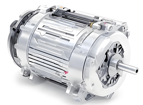
Brushed and brushless DC motors are two of the most common electric motor designs, powering everything from toys to electric vehicles. While both convert electrical energy to mechanical motion, their internal structures, performance, and use cases differ drastically.
What’s the Difference Between a Brushed and Brushless Motor
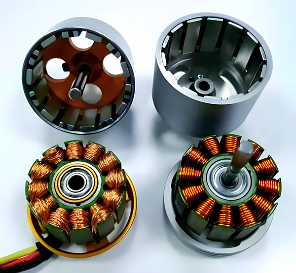
Brushed DC motors are reliable, but wear and tear over time can lead to failure. Whether you’re troubleshooting a power tool, household appliance, or industrial conveyor motor, knowing the signs of a bad brushed motor saves time and prevents further damage.
How to Know If a Brushed Motor Is Bad
